Tesla Coils
I have been building tesla coils since I was in high school and still haven't completely tired of it. Here is a summary of coils that I have built, in chronological order.
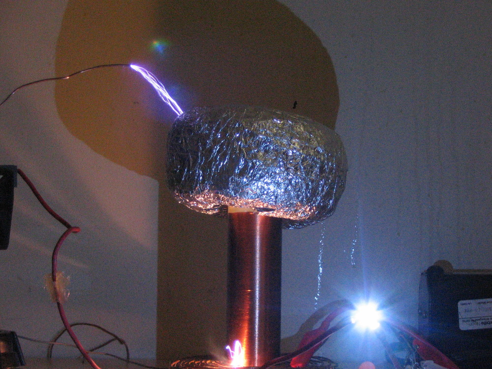
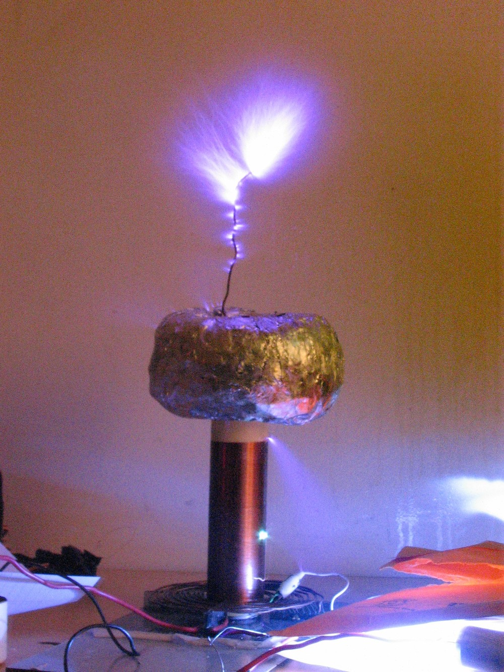
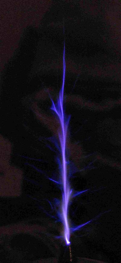
2005 - Small SGTC
This was the first coil I built, which was based on a small neon sign transformer. I used two bolts screwed into a piece of PVC pipe for the spark gap, and a small MMC of CDE film caps for the primary capacitor. Topload was a piece of 'pool noodle' wrapped in aluminum foil. Resonant frequency was about 1MHz, and it was good for a few inches of sparks and made a ton of noise.
Overall view:
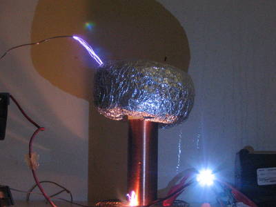
A longer exposure showing the streamers:

2006 - Small VTTC
This was the second coil I built, which was based around an 811A vacuum tube powered by a microwave oven transformer. I was tired of the loudness of SGTCs so I decided to experiment with CW coils and found them much more pleasant. This coil is virtually silent in operation since it runs on filtered DC and has a 1.5MHz resonant frequency. See this forum post for more details.
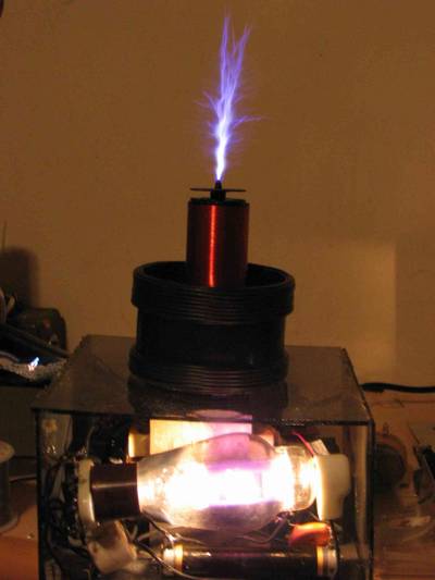
A single stremer:
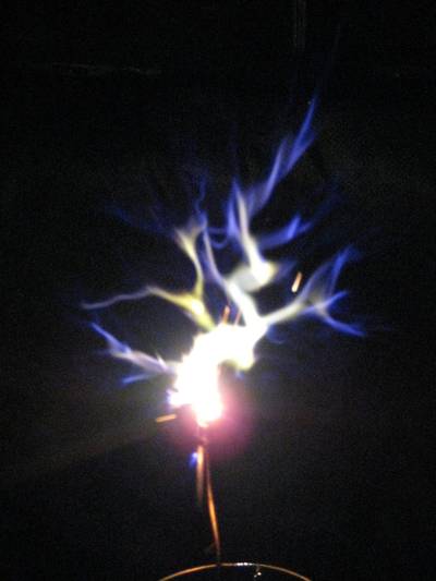
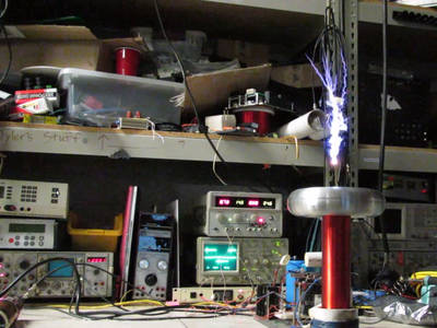
2007 - Audio Modulated SSTC
I built this coil based on Steve Connor's DWSSTC-II coil. After some experimenting I found that using a resonant frequency of about 400kHz gives a good compromise between background hiss (a problem at lower frequencies), simplicity (can use normal MOSFETs in a fullbridge with reasonable gate drivers), and reasonable spark length per input power (this seems to drop with increasing resonant frequency for CW coils). To get good audio performance I generally tune the coil to pull 1kW when run exactly at resonance (maximum power draw from the wall), and then detune the PLL so that the quiescent power draw is 500w. This leaves plenty of room for the audio modulation and gives reasonably clean sound loud enough to fill a room. Furthermore, I have found that leaving the PLL disconnected (and just using the CD404046 as a VCO, without the phase detector/error amplifier) works fine for these coils, since they are heavily loaded and thus quite insensitive to tuning (the audio modulation alone represents about a 10% drive frequency shift!) and being driven off resonance anyway. This simplifies construction since you do not need to fiddle with the antenna to get a feedback signal.
See this forum post for more details.
A streamer:
After I moved off to college I decided to build a clone to leave with their electronics club, IEEE@UCSB for demos. The design was more or less the same as the first one, with a topload made of a stack of hard disk platters. We eventually made a wooden box for it to keep fingers away from the mains voltage, but I can't find any pictures of the final coil.
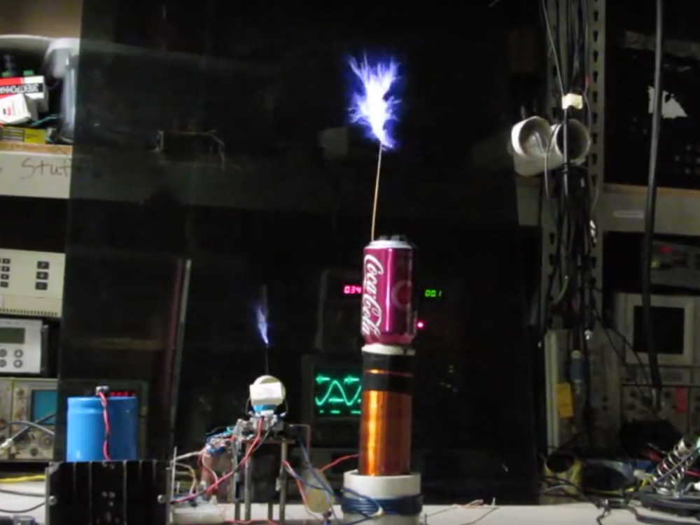
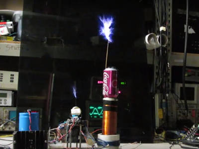
Another school, another coil. I made this clone to leave at MIT, this time using an empty can of my favorite soda as the topload. This earned the coil the nickname 'Cherry Cokinator' which has stuck with it even after the soda can got replaced with a traditional toroid which was donated by OneTesla.
Here is a photo of the original coil running with audio modulation (at about 500w power), and a shot of the coil with its upgraded topload running with no busscap (just about 30uf of snubber on the bridge) on fullwave rectified mains at about a kilowatt.
I also uploaded a short video of the coil playing some pop music to youtube, and another clip of the coil running without its main DC bus cap which gives much longer sparks and an angry sounding 120Hz buzz. Funny thing about the first video, it received a DMCA takedown notice, not from the actual artist (Taylor Swift) but rather by an teenage artist who had 'covered' the original song. I was able to keep the video up by agree that the ad revenue from the clip would go to the aforementioned artist which is better than nothing I suppose. In both of those clips the coil excitation signal (into the gate drivers) is provided directly by a FM capable function generator (tektronix FG502 sitting in the background), with the audio fed into the VCO in port (no PLL). I have since replaced the function generator with a CD4046, also running in open loop (no PLL) mode.
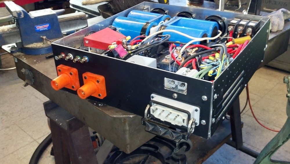
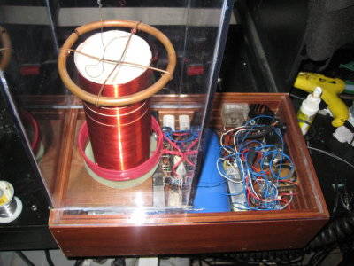
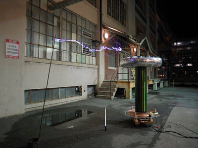
2015 - YottaCoil
This was a group project built at MITERS. The coil originally started out based on Fin Hammer's Hammertone "Predikter" design driving a fullbridge of CM1000HA-24H IGBTs that we got for cheap, but we later switched it over to Steve Ward's Universal DRSSTC Driver 2 (donated by GGY) driving a pair of CM300 halfbridge modules. This was largely because the CM1000 bridge really was overkill for the limited power we could find (50A 208v service), but also partially because we observed some random failures of the CM1000s that we could not explain that went away with the CM300s. Topload is the traditional ventalation duct around a bike rim, and the primary cap is a MMC of EFD 4uf/600v snubbers. We initially ran from a voltage doubler after a large variac, but have switched to a MDX-L6 'magnetron supply' capable of 6kw power limited output up to about 800v DC which we got for $5 at swapfest. The 6kw power limited output is nice since it means there is no risk of blowing our upstream breakers, but we are also investigating building a dedicated boost converter so that we can get a bit more power (our breakers are good for 10-20kW depending on where we run the coil).
In any case, here are some pictures of the system:
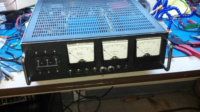
Here is the driver mounted up in a nice box with panel meters and blinking lights. I also tried to squeeze a boost converter into this box as well, but that turned out to be a miserable failure so I am have since removed boost converter and just left the voltage doubler and inverter in this box. The 2-pin anderson connector out the back is connected to the DC bus, and will allow me to run the coil from an external DC supply. The large orange camlocks are for the primary connection, and the 6-pin connector is for the AC in.

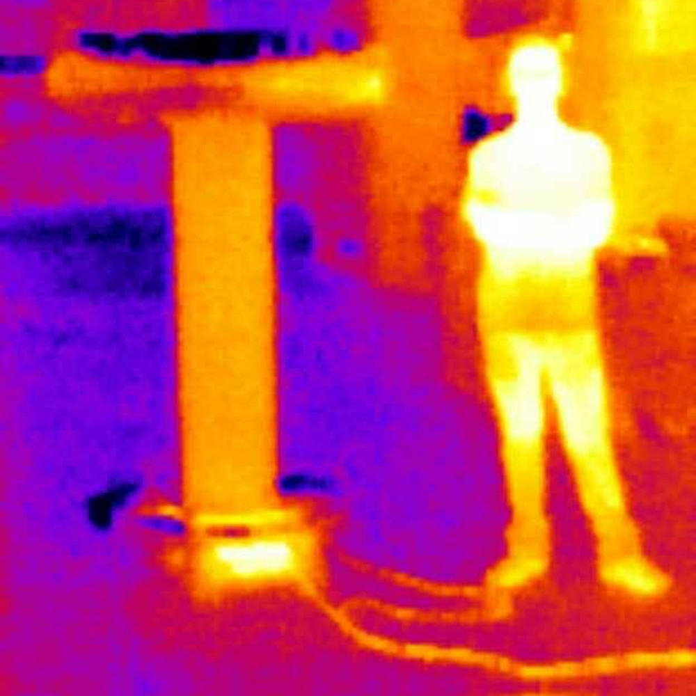
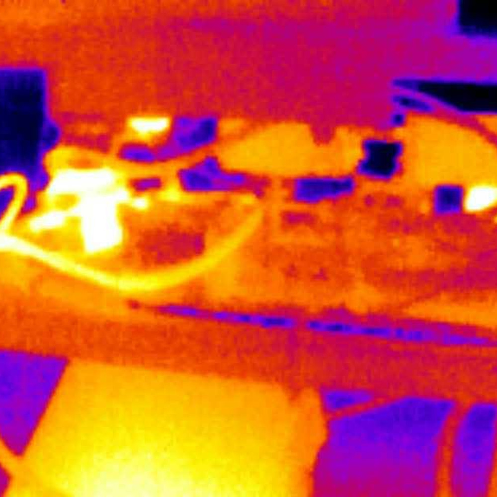
Here are some shots taken with a Seek thermal camera showing the resonator and bridge after a run. The tank cap (the hot blob at the bottom of the left image) is lukewarm, we suspect this is largely because the clamping arrangement we used acts as a shorted turn under the primary so there is significant heating in it. It is also possible the caps themselves are being induction heated, or just being heated due to dielectric/ohmic losses-they did have over a megawatt of peak power circulating through them. The next hottest component was the bridge rectifier (the hot blob in the right image). Other than that the warmest part of the coil is the #00 size wire connecting the bridge to the resonator. The warm item in the bottom of the right image is an analog oscilloscope we used to monitor the peak current during operation.


You can also find a youtube clip of the coil (running indoors with a 400v DC bus) on youtube.