
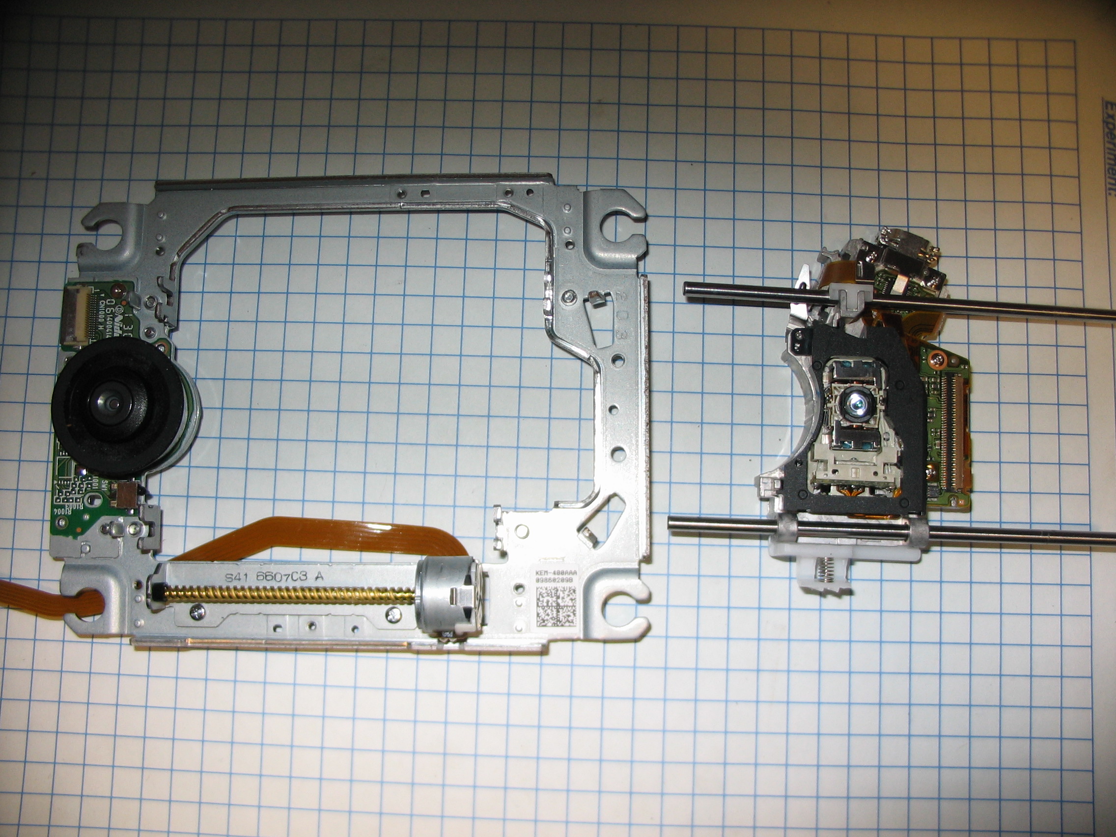
This page shows the complete disassembly of the optical assembly out of a Sony PlayStation 3, p/n KES-400AAA. It is sitting on 1/4" graph paper for scale. I apologies for the odd lighting, my camera's flash does not work with macro shots.
For more information on how the optics work, and what to expect from the violet/UV laser diode, see Leslie Wright's page
I took these photos as I was working on extracting the 405nm/650nm/780nm laser diode module, which I wanted to use in my RGB laser as the blue laser, and some of the optics. The rest of the drive was of little value to me, the mechanical components are nice but far from useful and the electrical components were not worth salvaging.
Click for a larger image.
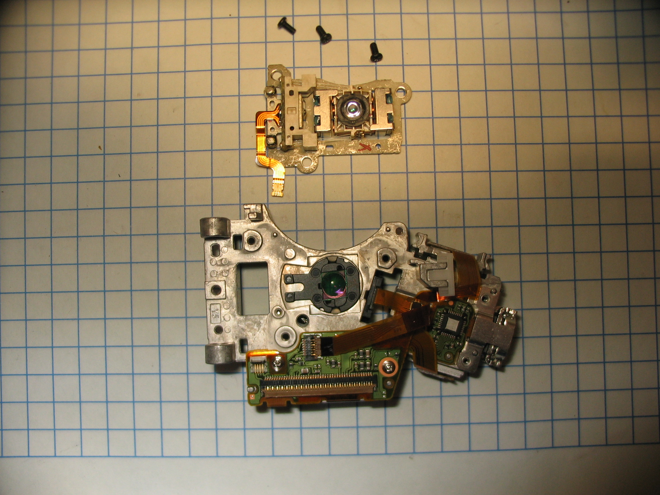
Top view of the assembly:
Remove the 4 stamped steel brackets, by removing 4 small screws.

Remove the 2 plastic brackets, by removing 2 small screws.

Carefully lift out the optical assembly.
Remove the tracking and spindle motors, by removing 5 screws.
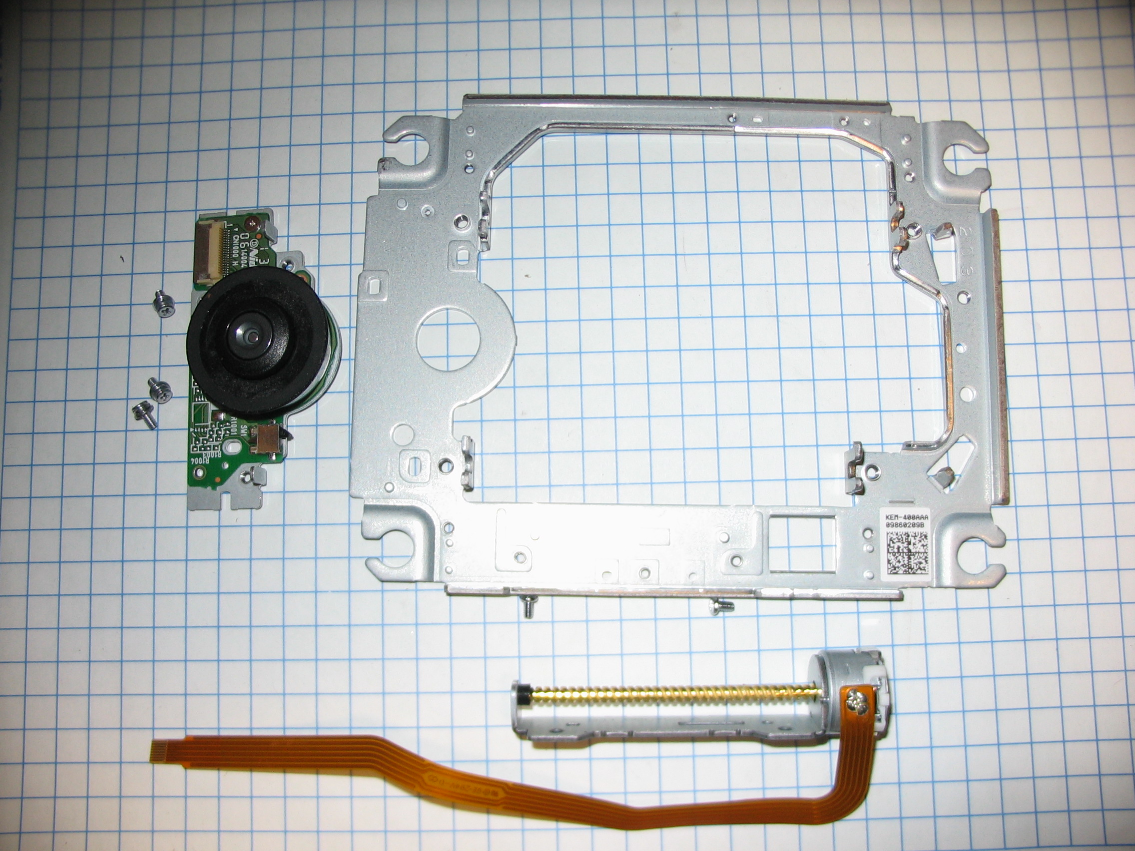
Slide out the 2 rails from the head.

The plastic bumper can be be removed:

Flip the head over:
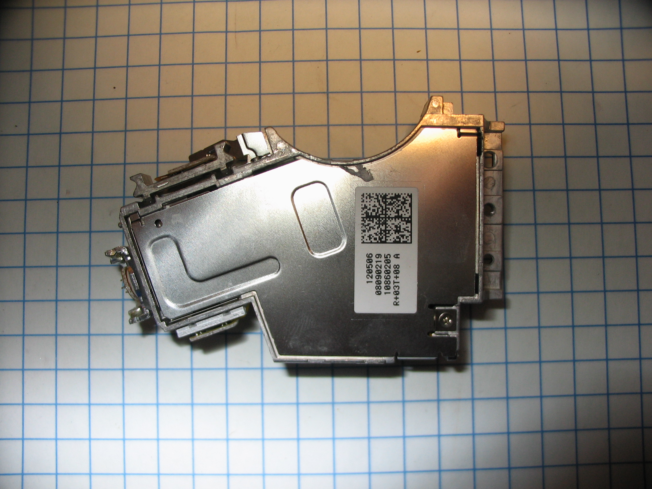
Remove the screw, and lift off the dust cover:
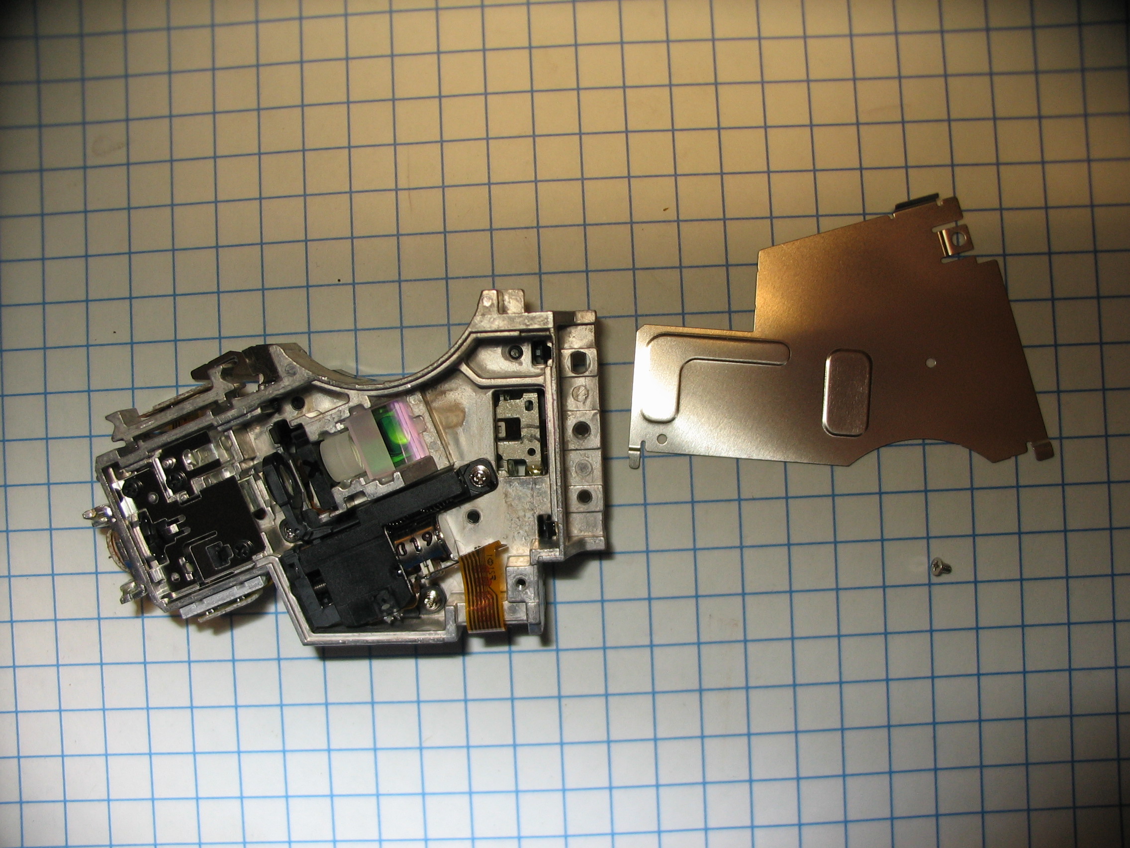
Flip it back over, remove the small clip:

And then the plastic guard:

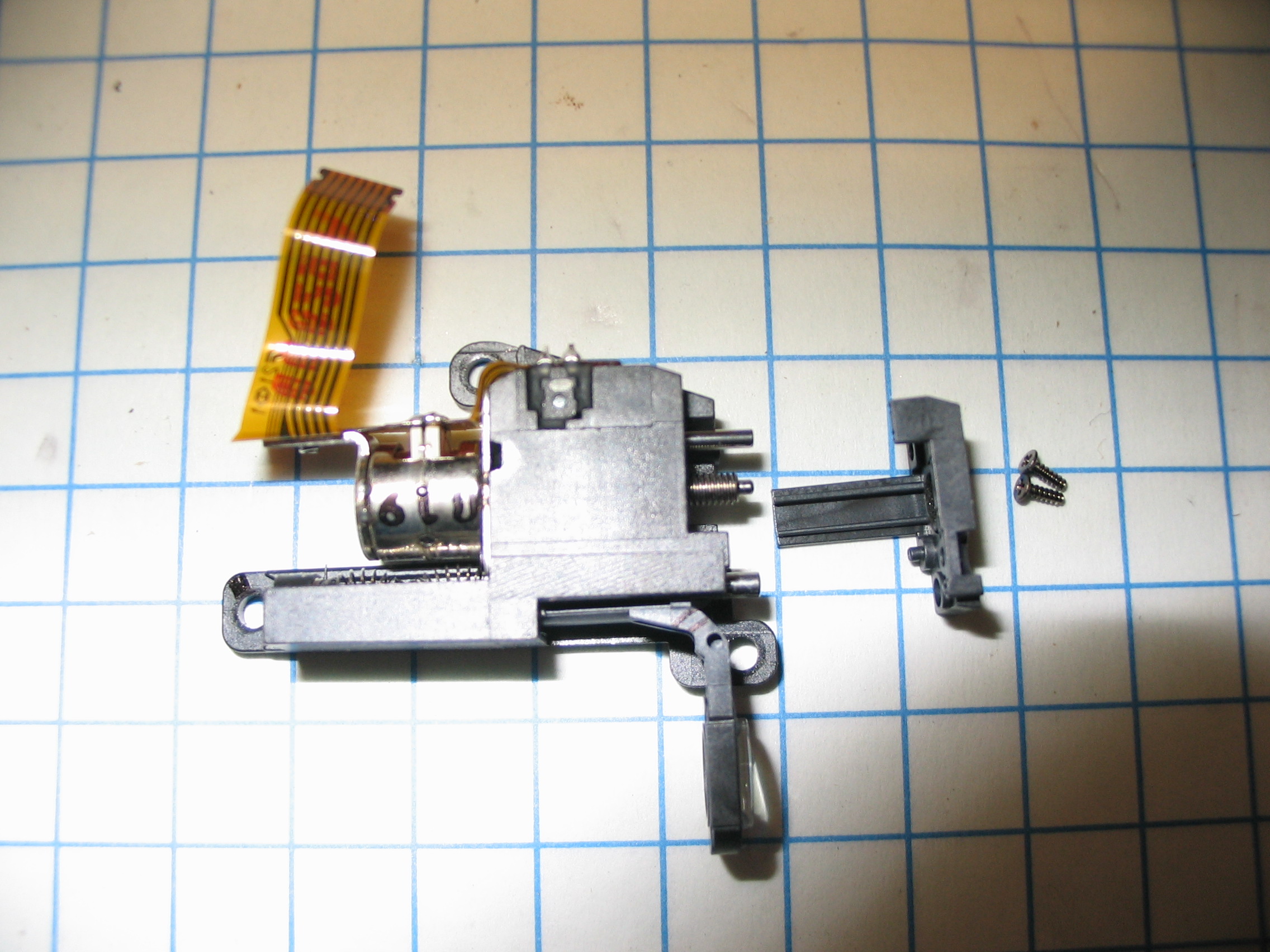
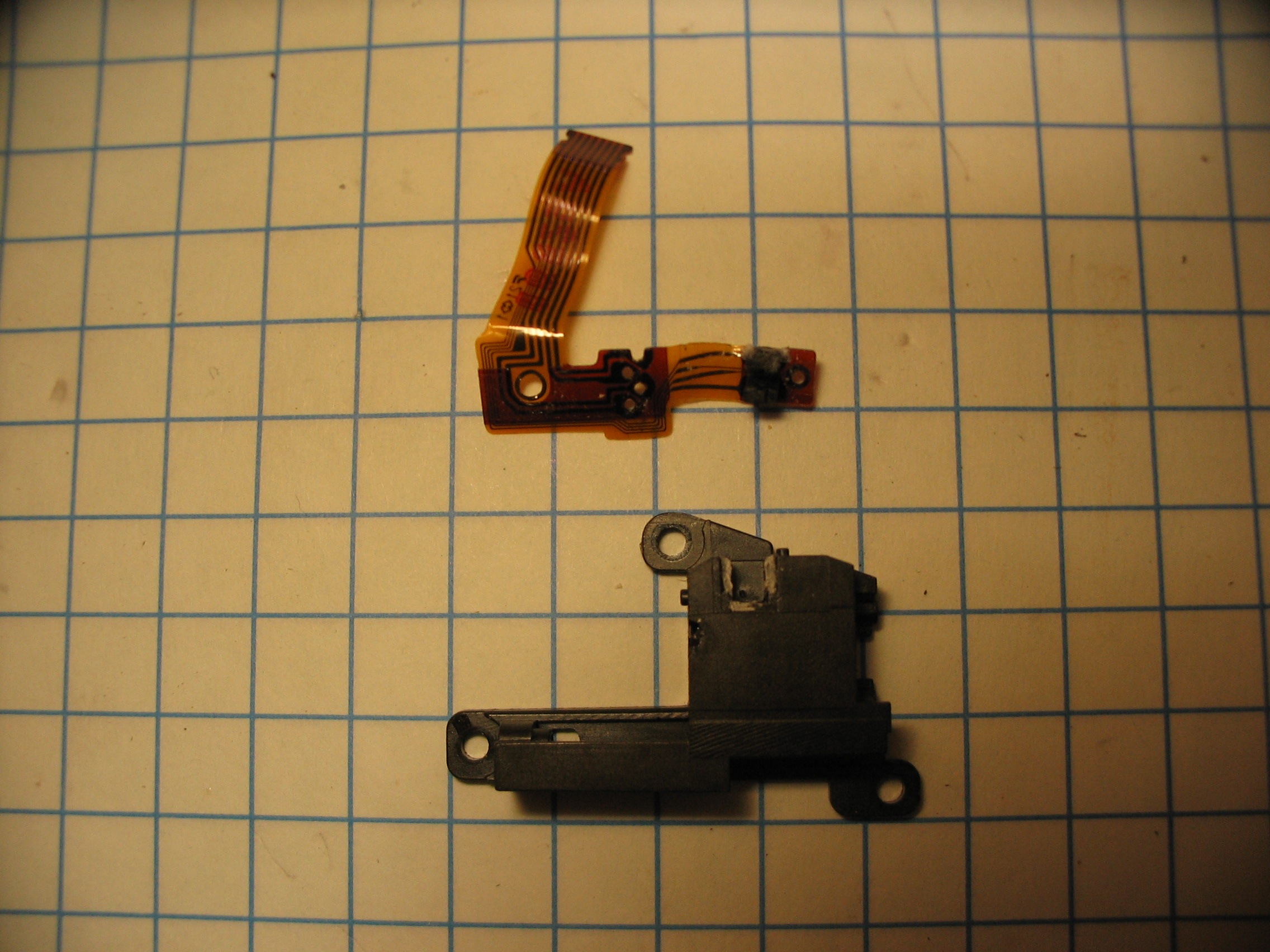
Unscrew the tracking assembly, open the connector (the brown tab snaps up, and the cable slides out), and lift off:
Flip it over again:

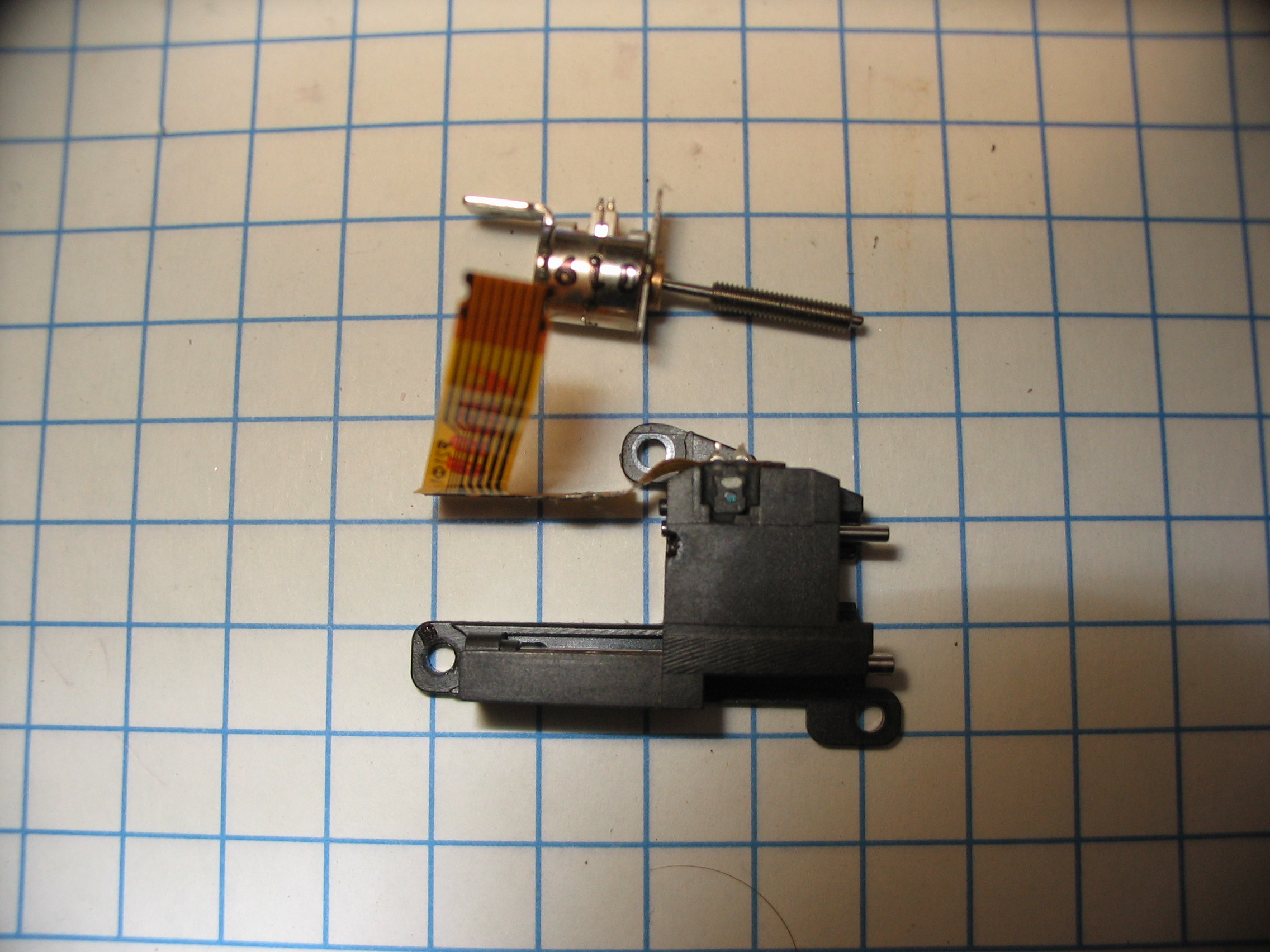
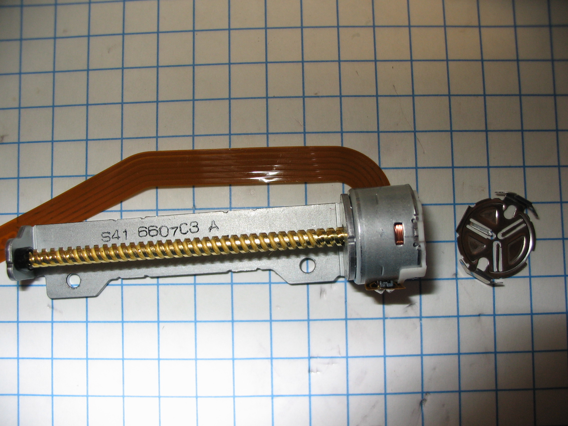
Unscrew the focusing motor:

Remove the 2 small screws, and slide off the top:
You can then carefully unscrew the threaded ring, and slide the lens holder and spring out:

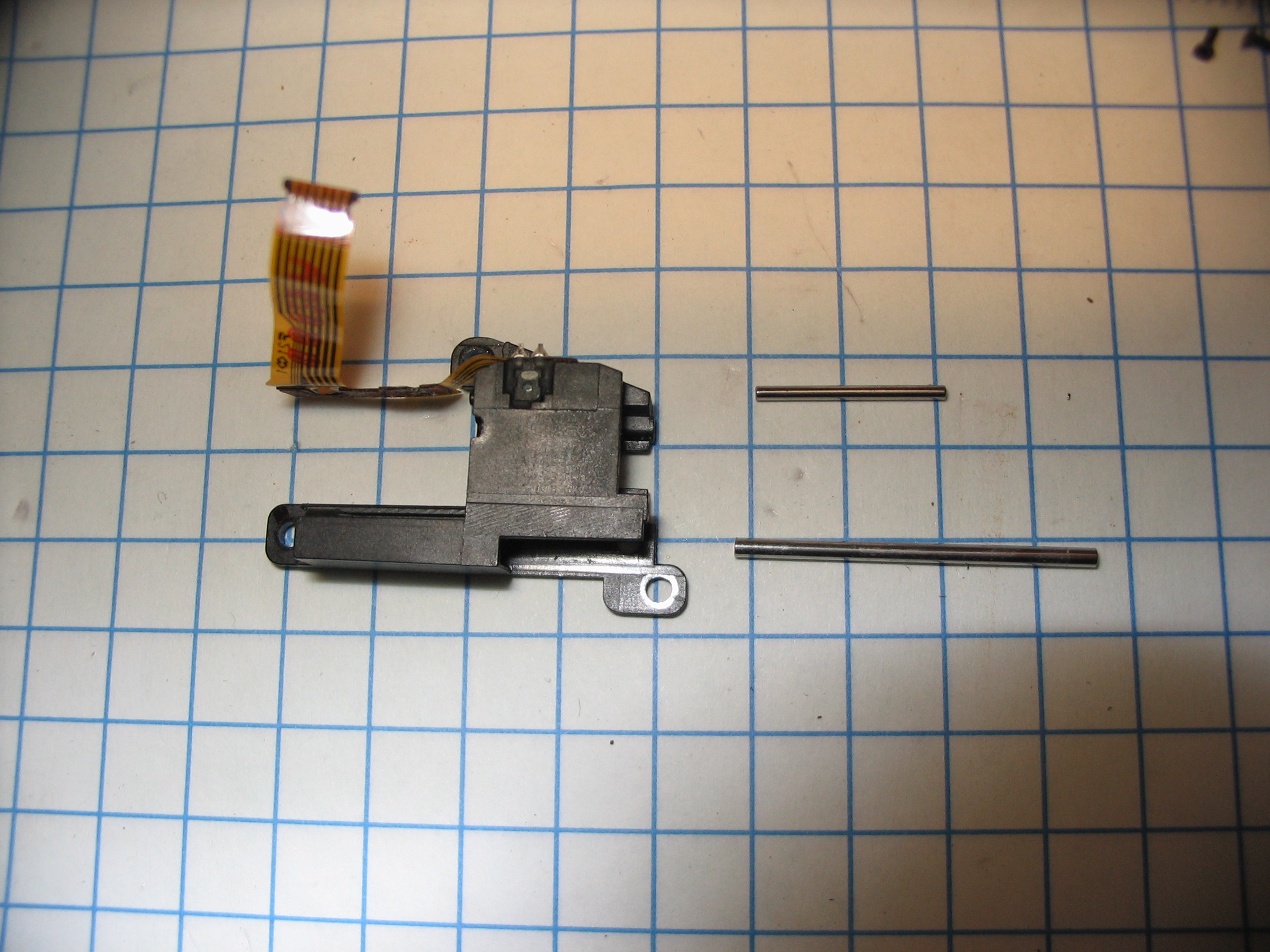
Unsolder the flex from the motor (carefully, the pins are not attached well to the windings) and unscrew the motor:
Press out the 2 metal rods:
The photodiode can now be removed (it is glued in):
And unsoldered:

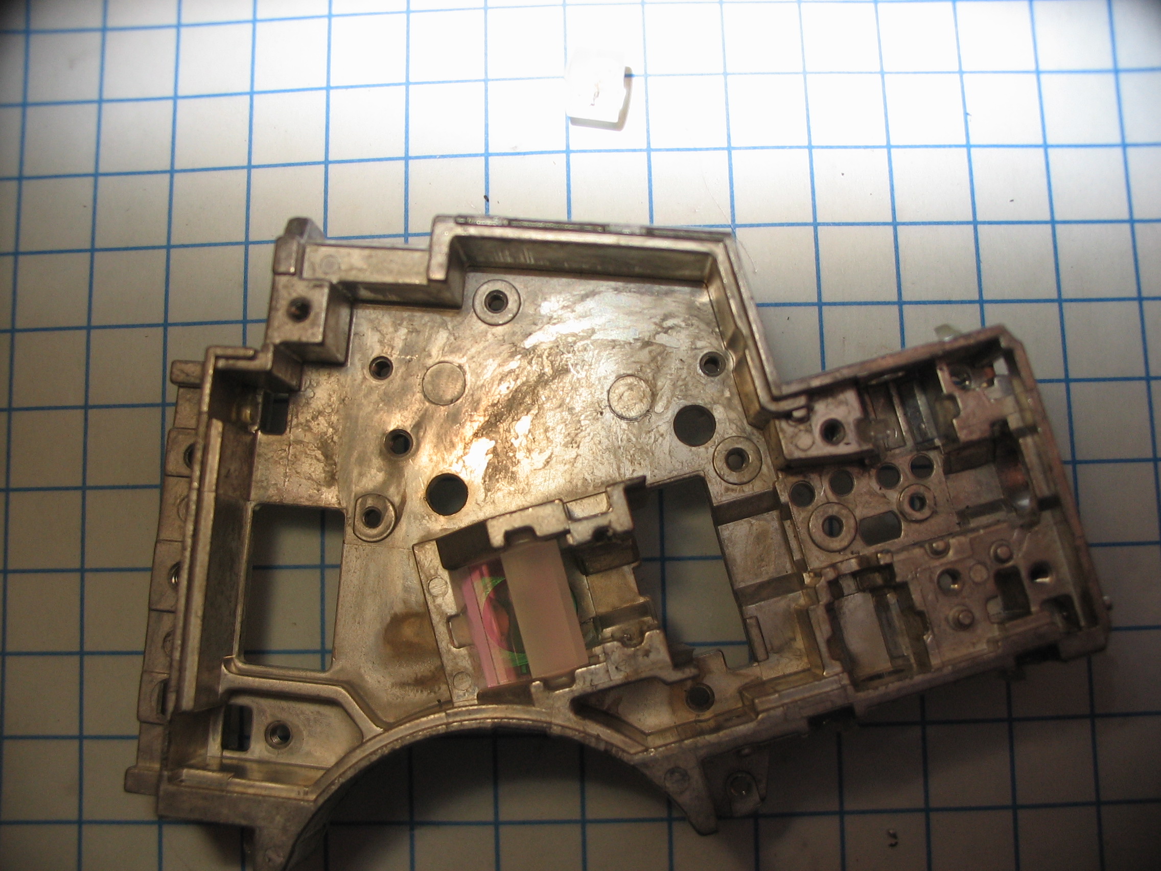
Unscrew and remove the metal plates over the optics:
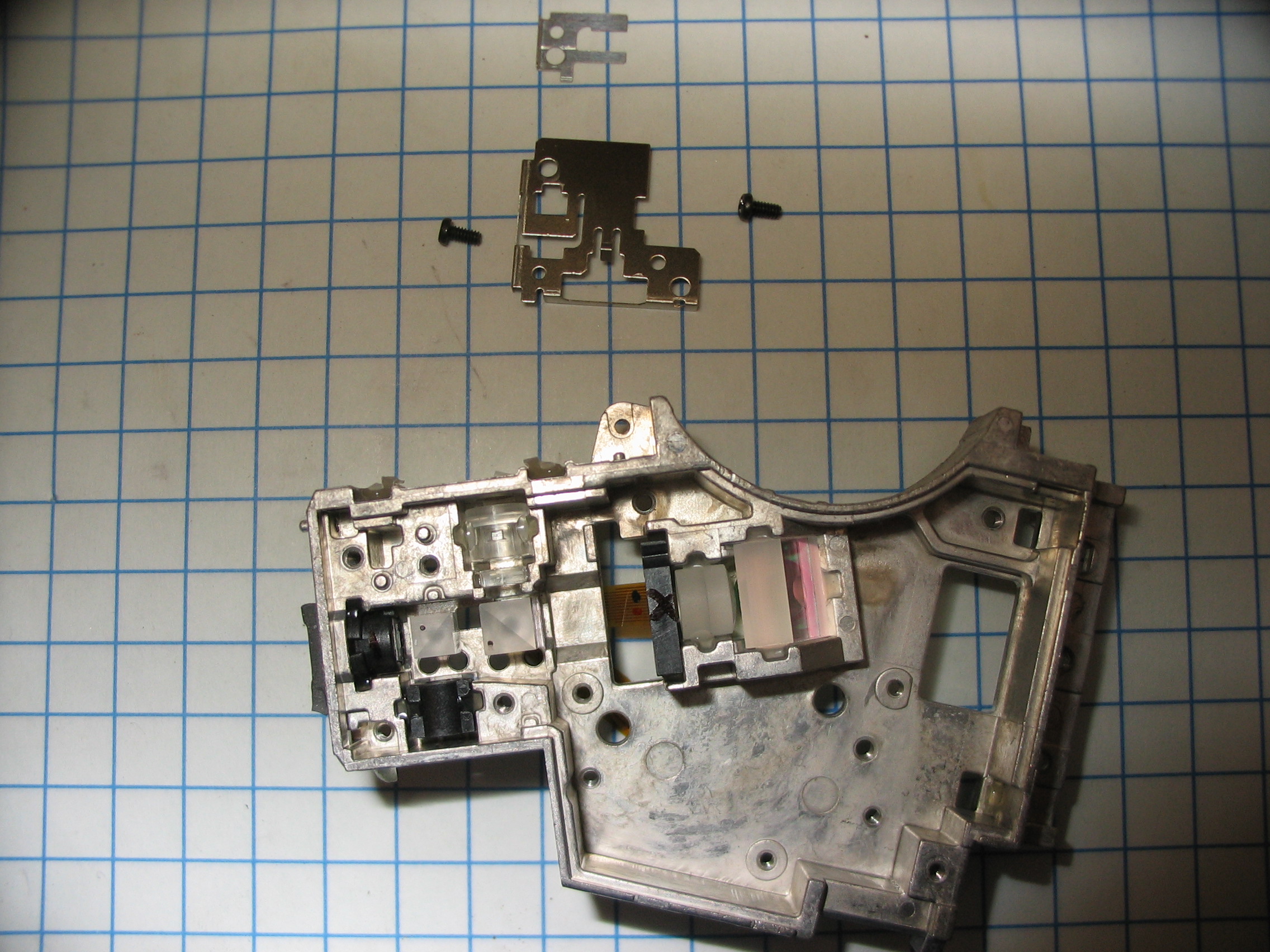
And remove the foam where the laser diode was:
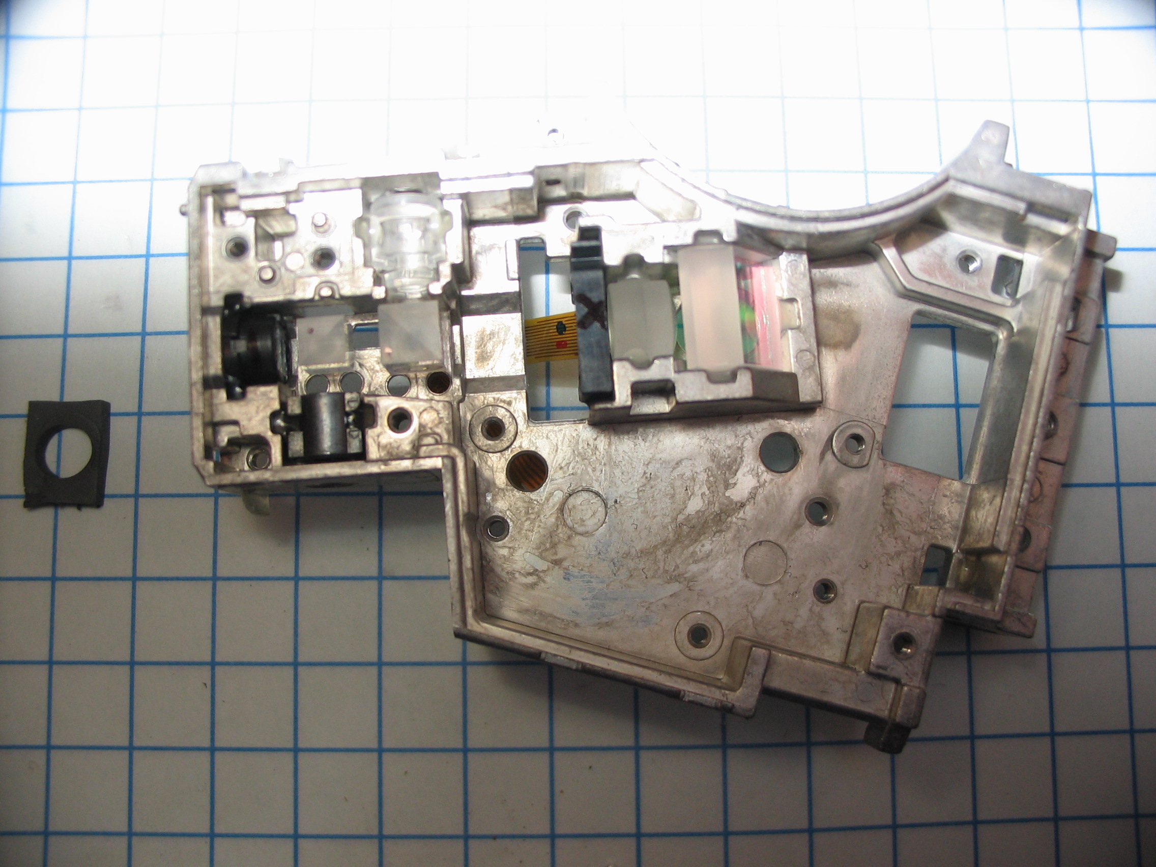
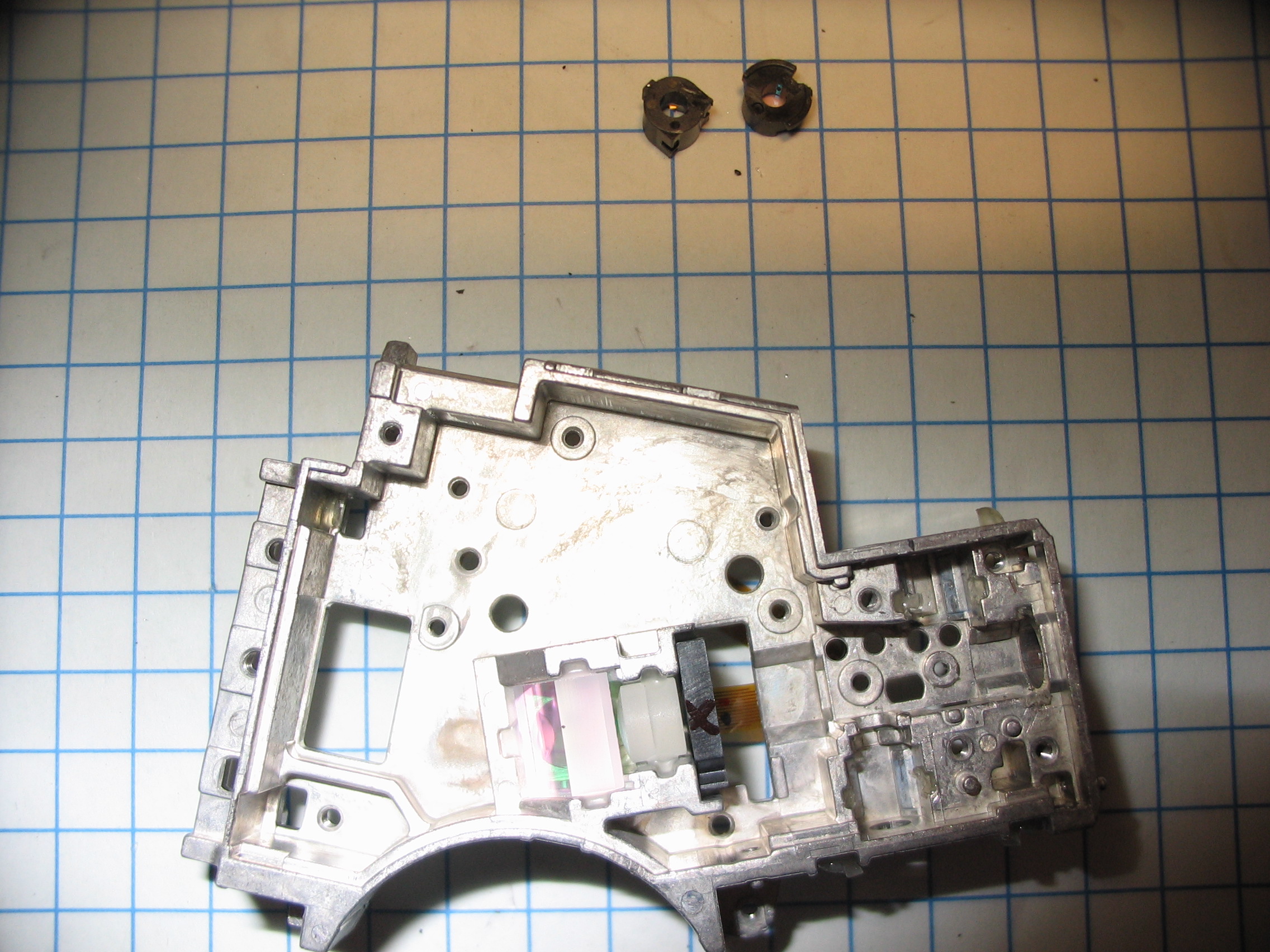
The 2 cube beamsplitters can now be removed (use a plastic tool to avoid chipping them):
Next up are the sense optics:

And the diffraction gratings:
Out comes the LCD (sorry it is blurry):

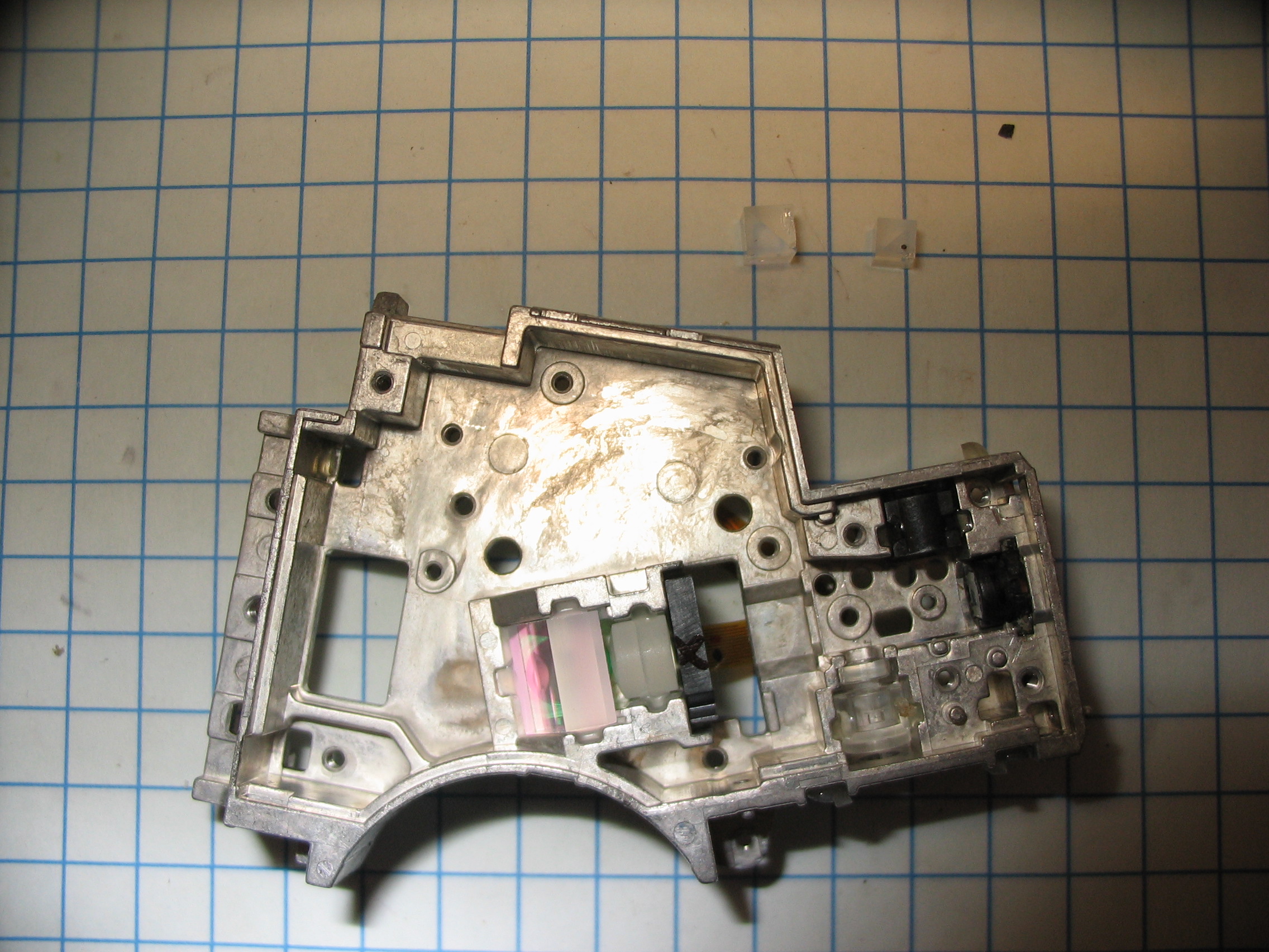
And another focusing lens:
Then the flip it over and pull off the window:

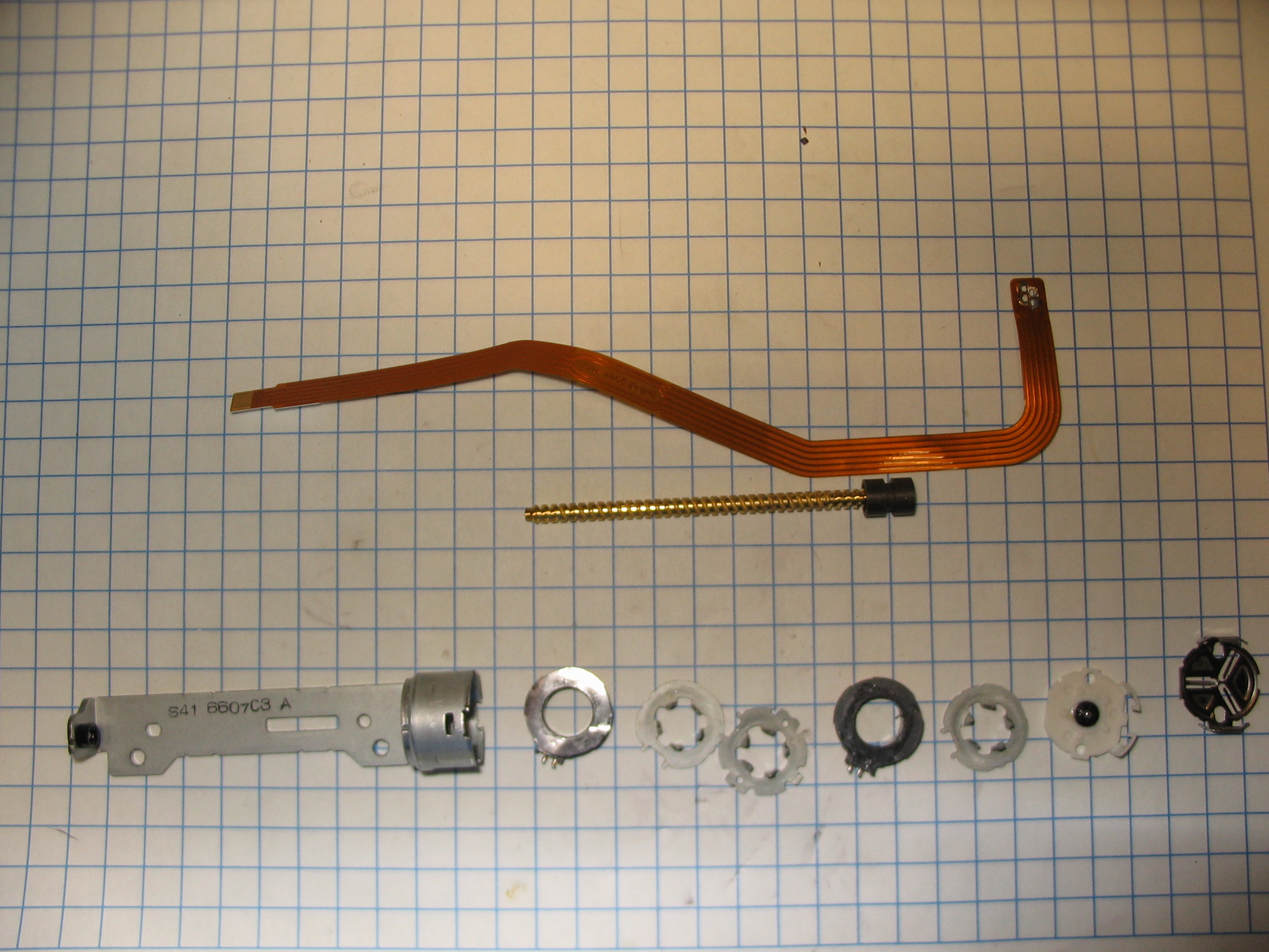
Now you can punch out the brass sleeves:
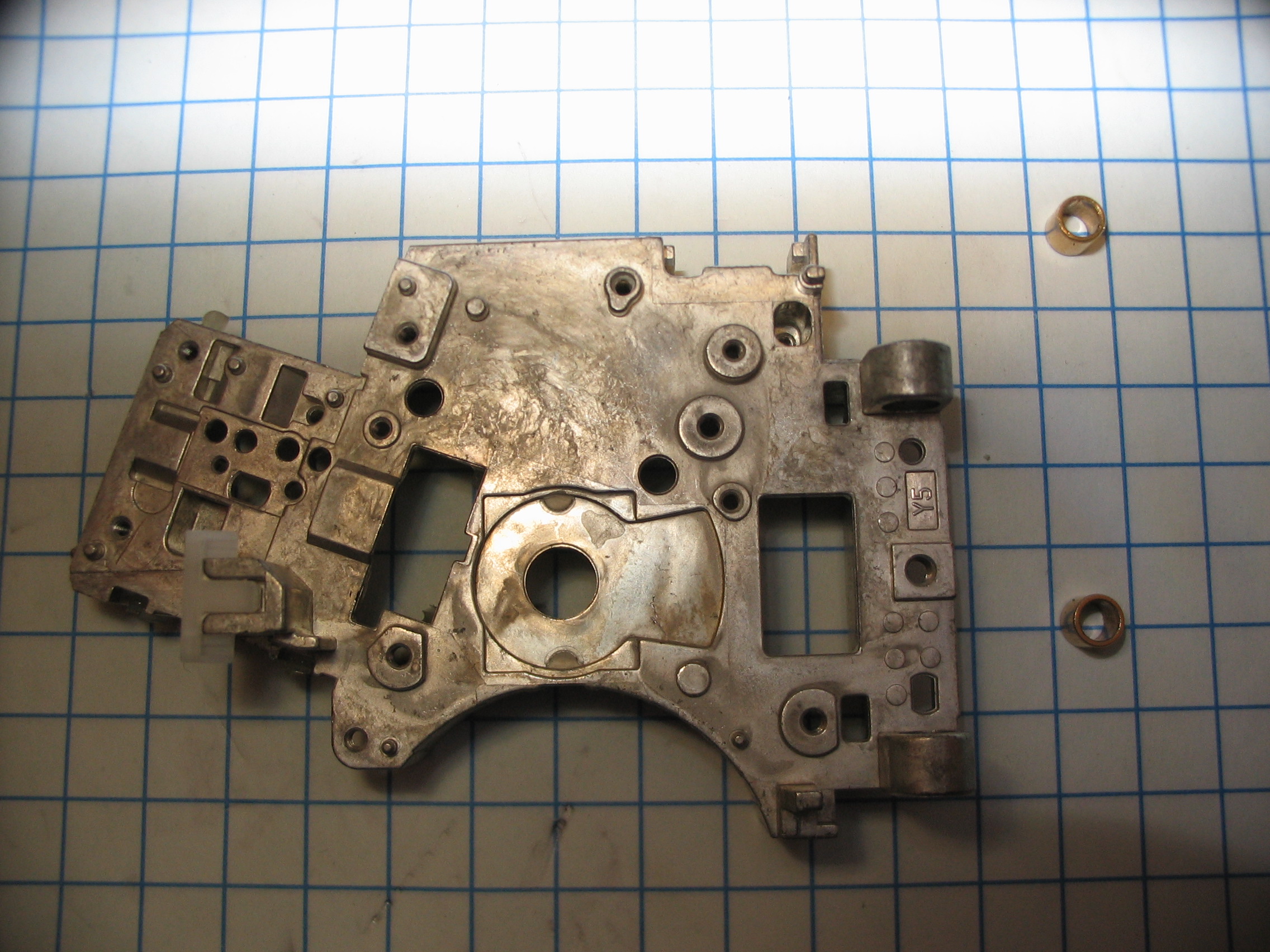
Snap off the cover plate:
The bearing can now be removed:
And then screw/armature slides out:
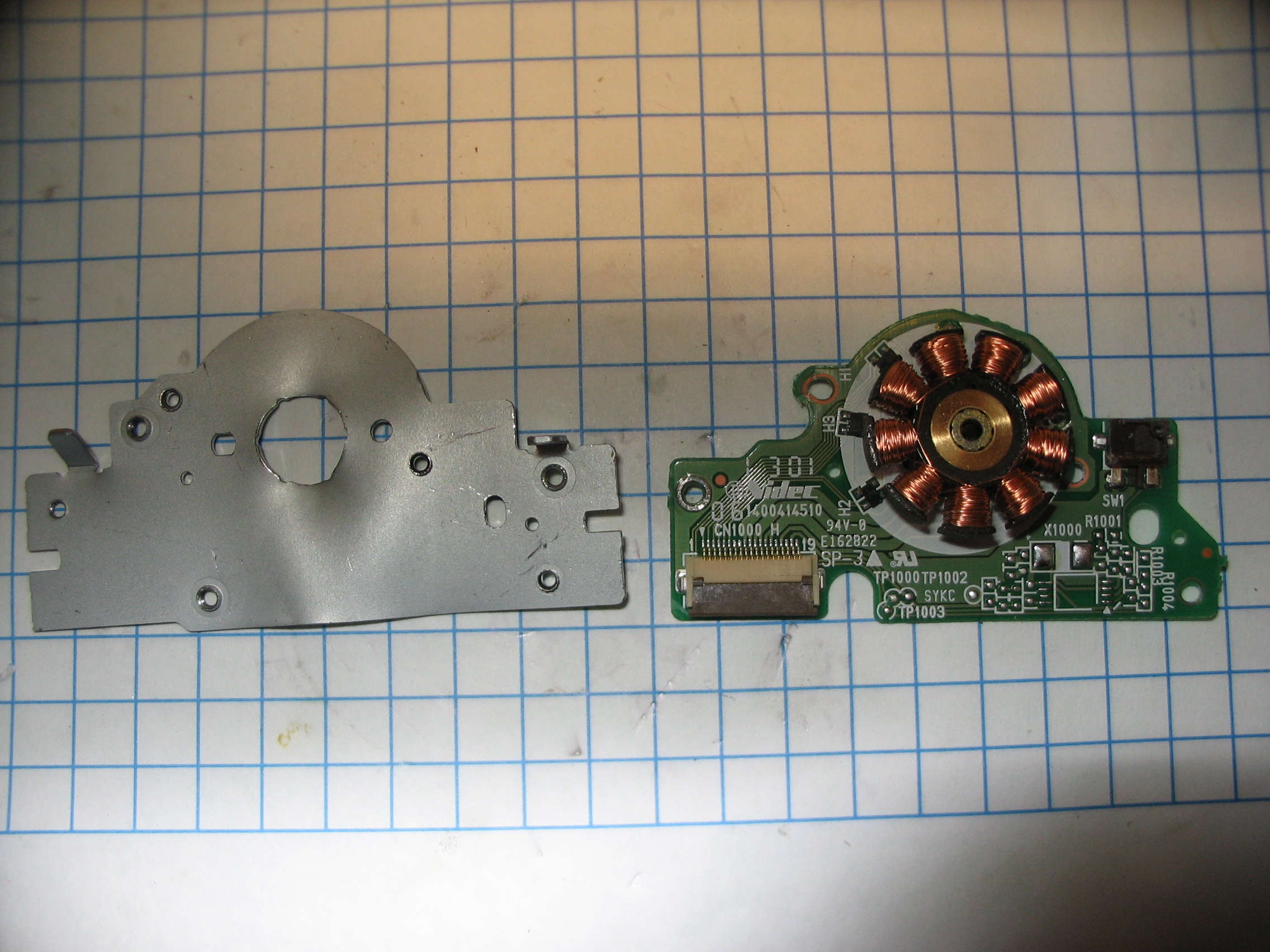
Then the 1st plate can be removed:

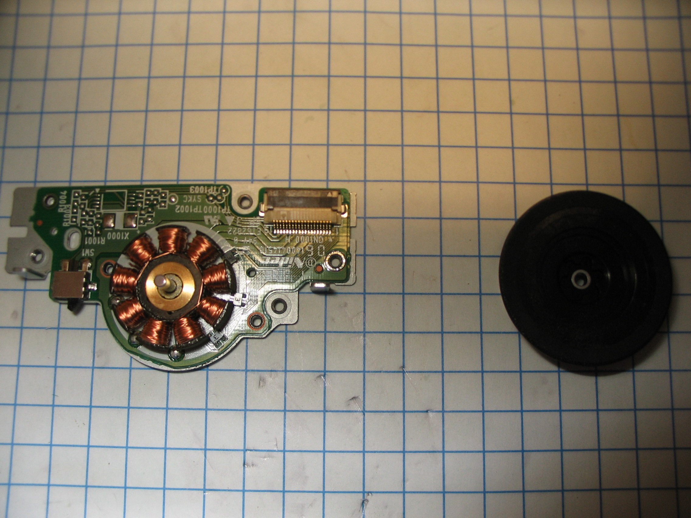
Now the flex must be unsoldered:
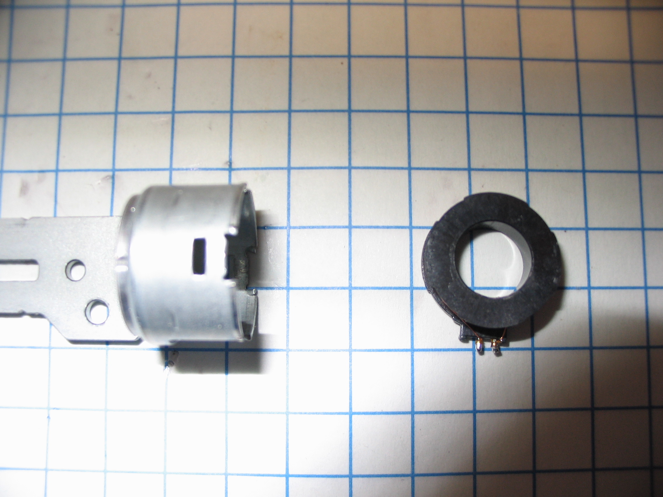
And then the 2nd plate can be removed:

Which allows the 2nd coil to be removed:
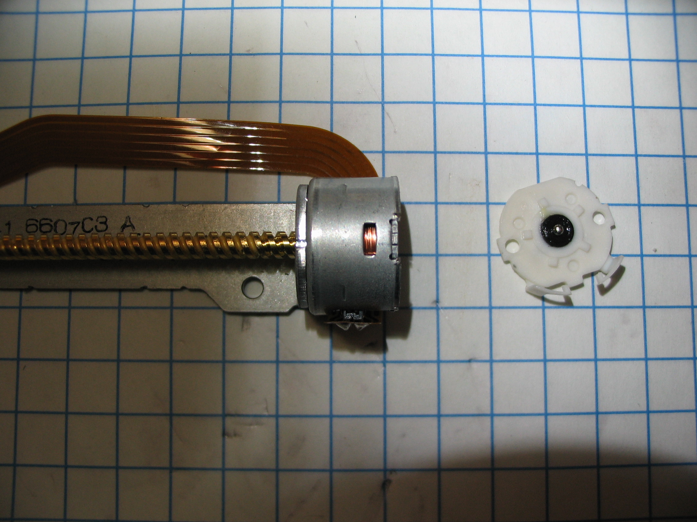
Overall View:
First the top cover must be removed:
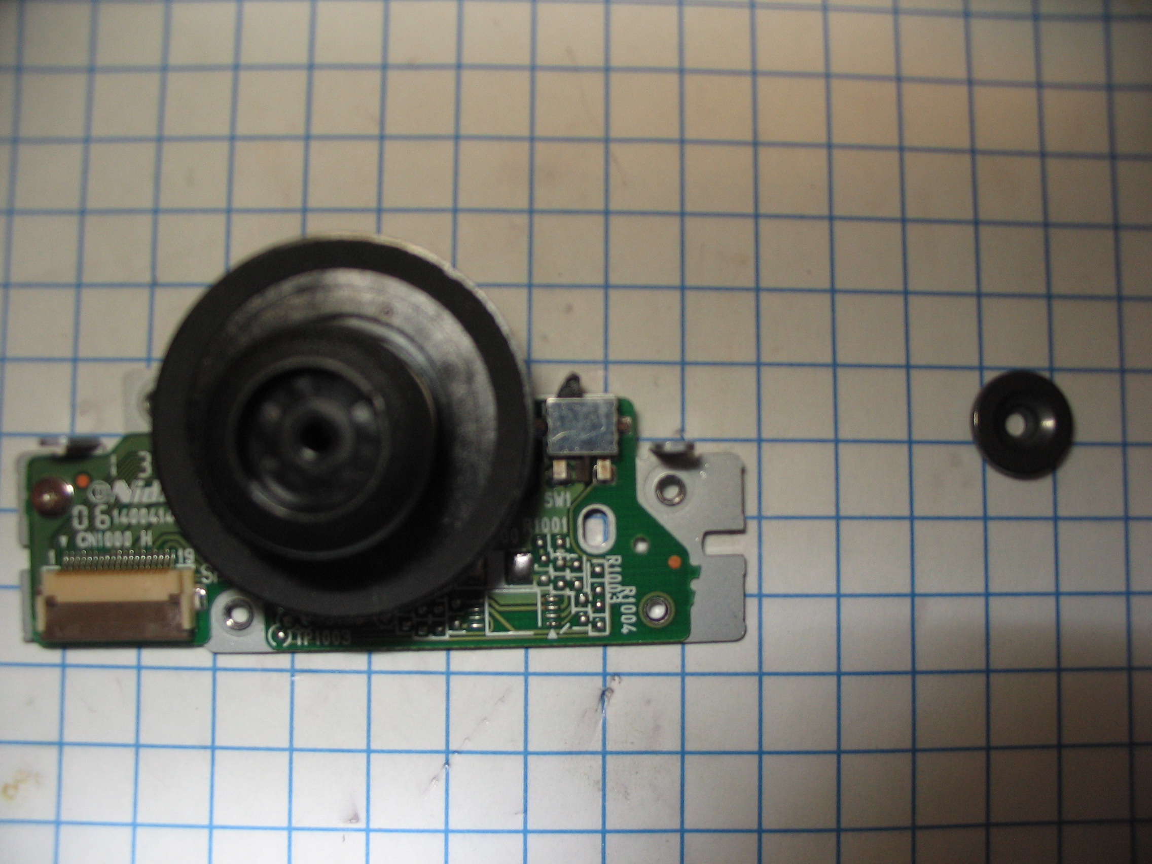
Then the centering code can be lifted off:
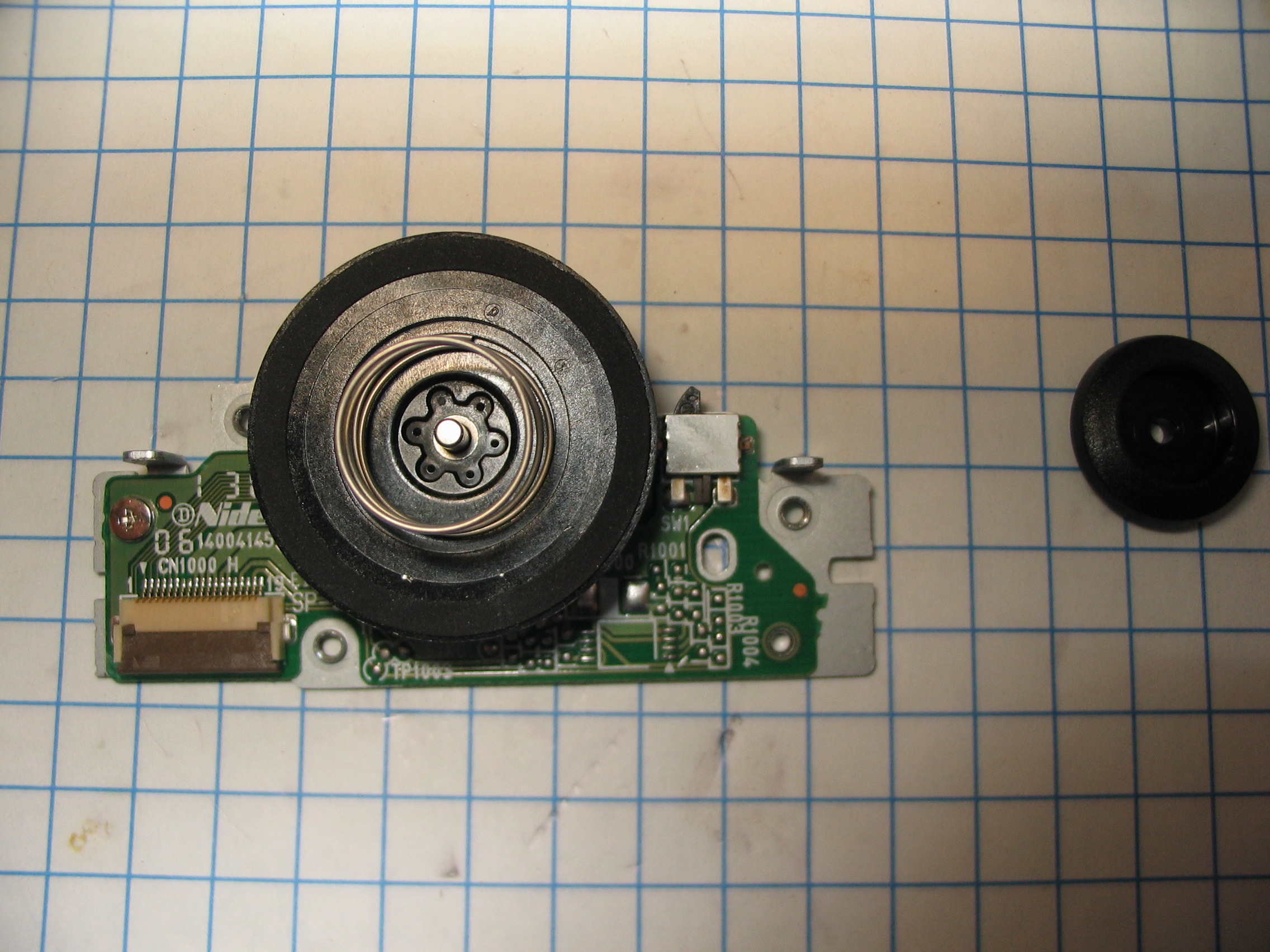
The spring can now be lifted off:

There is a small screw that eventually needs to be removed:
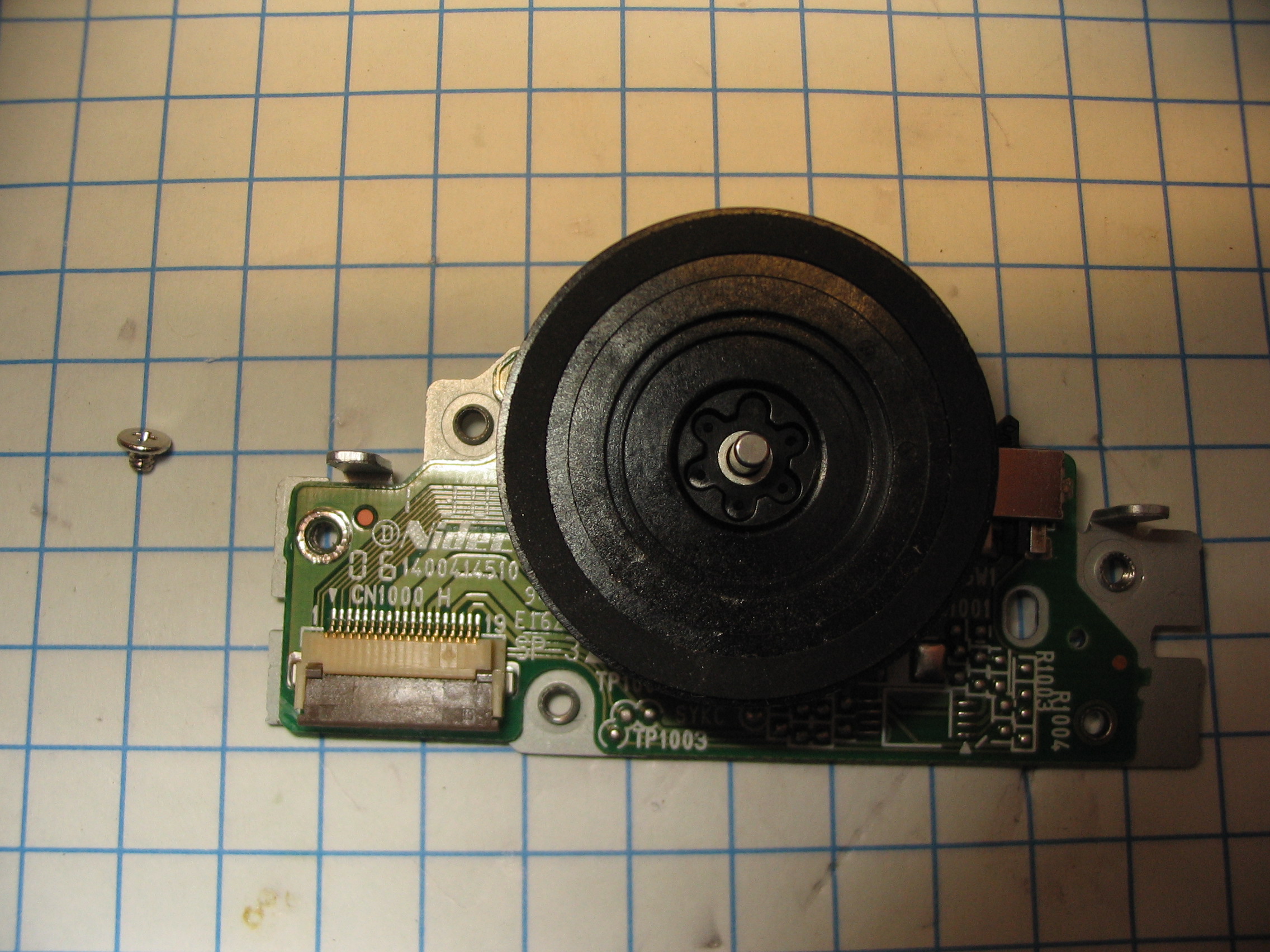
The thrust disk can then be carefully pried off:
The bearing must be forced out of the mounting plate:
The bearing can then also be pressed out of the motor windings:
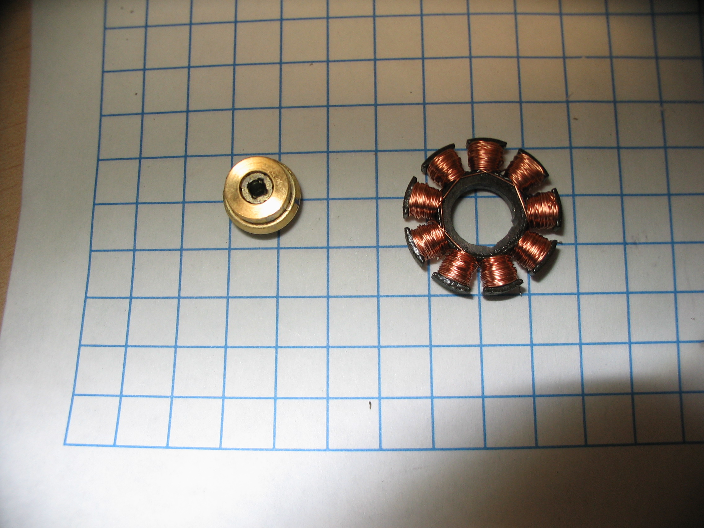
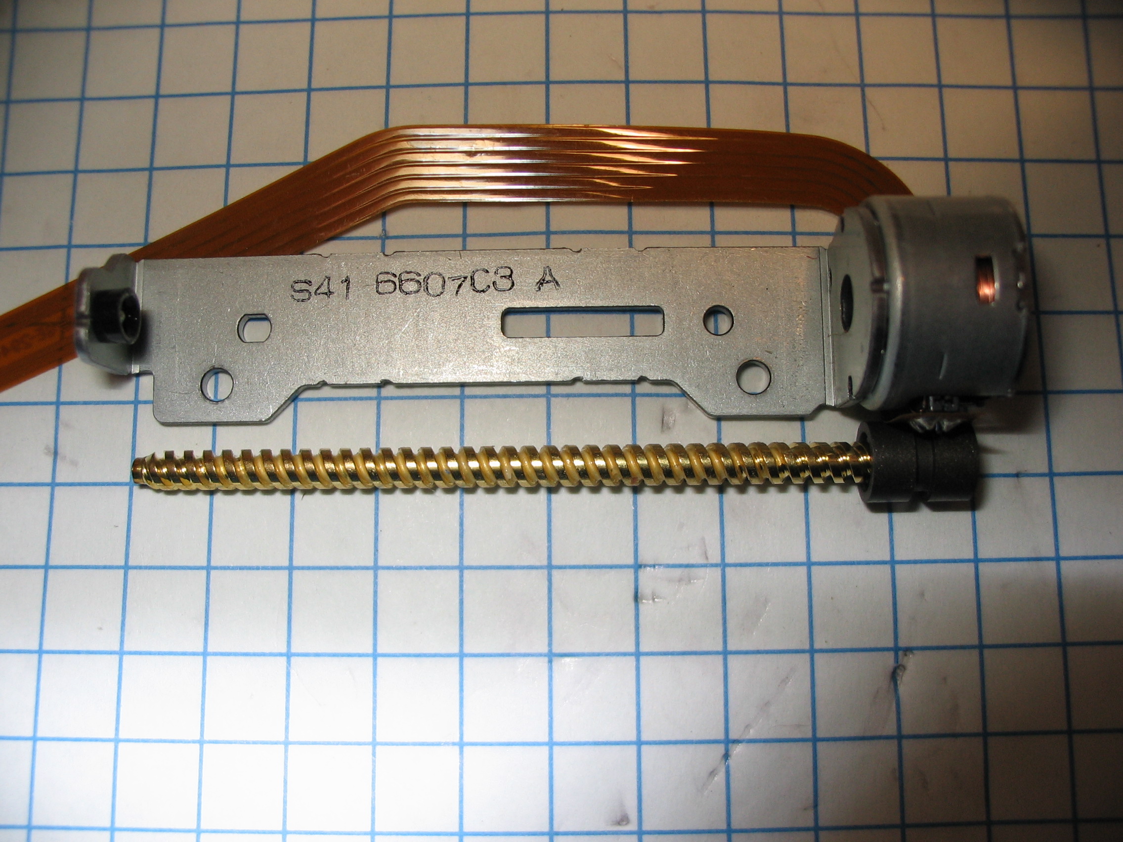
Overall View:
First snap off the 2 stainless steel clips:
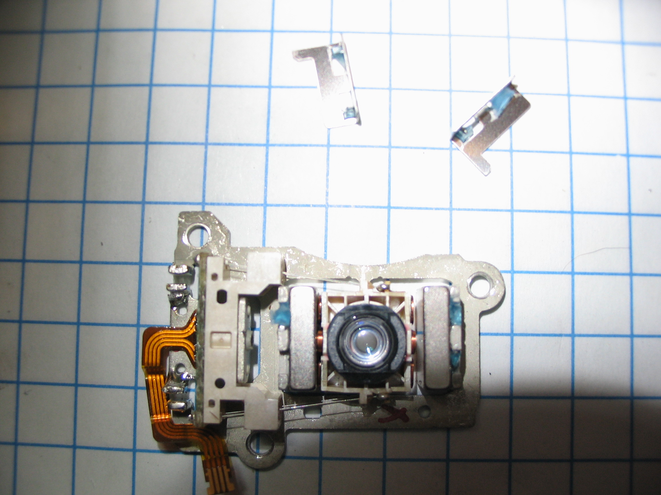
The lens/coil assembly is soldered onto the frame at 2 points near the flex connector:
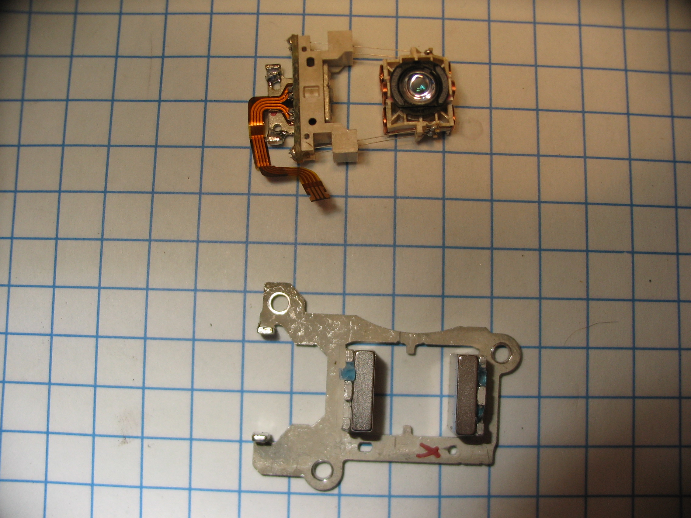
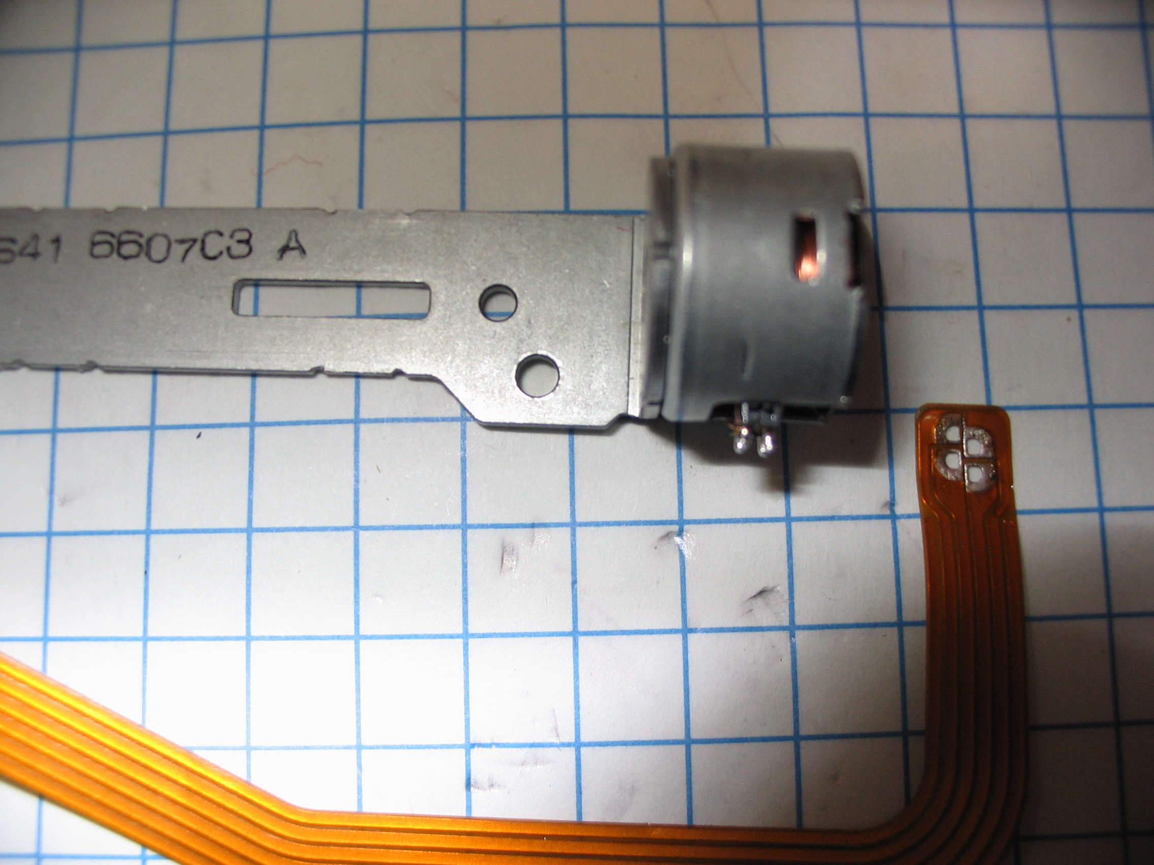
The tracking head:

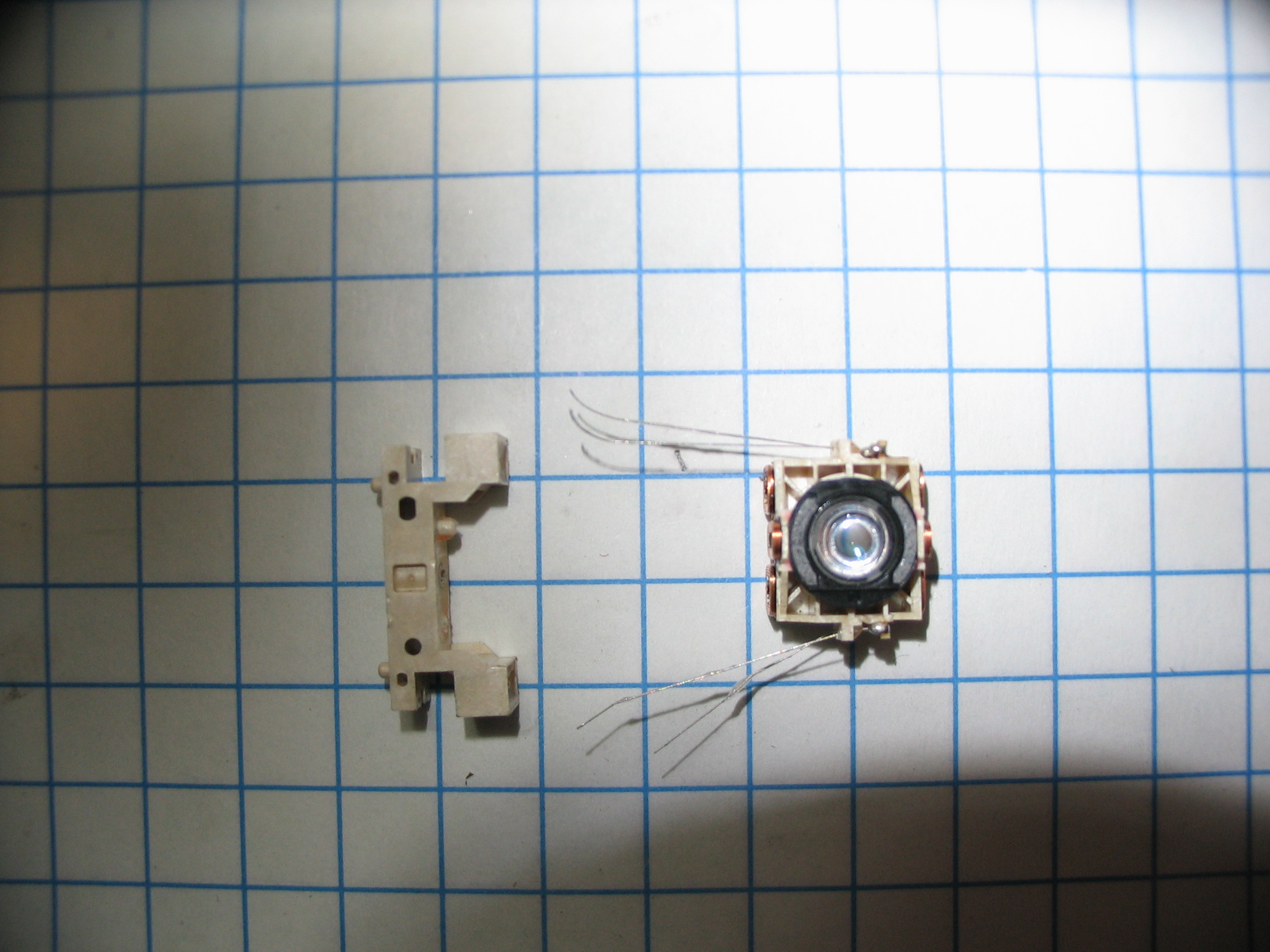
First the 4 fine wires must be unsoldered:

They can then be pulled out of the frame:
The laser diode (which has 405nm, 650nm, and 780nm laser diodes as well as a power monitor photodiode in the same can):
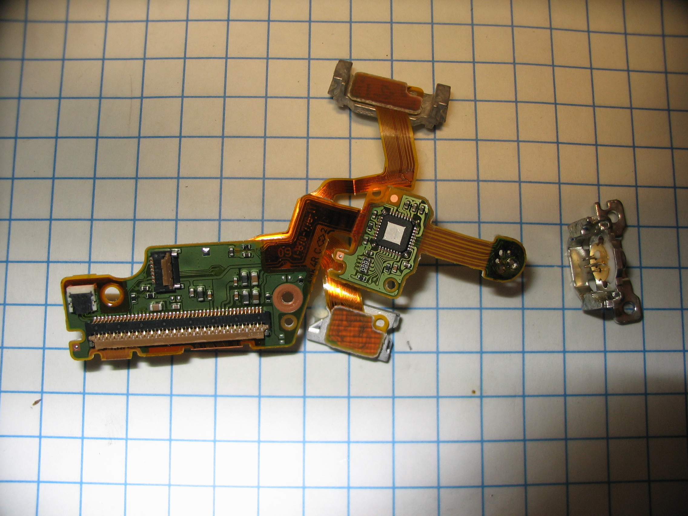
Last the tracking photodiode arrays can be removed:

I can be contacted at contact@krazerlasers.com