I once ended up with a large amount of bare 50W laser diode bars, and a need to mount them, which turned out to not be all that bad. After I did a little research I ended up at Robin's site, die4laser.com, which had some information on mounting bare laser diodes.
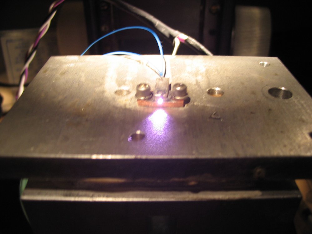
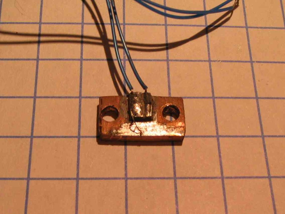
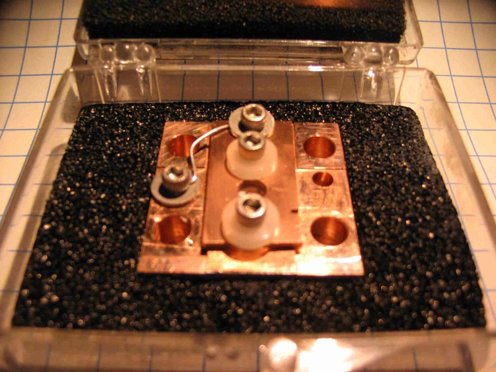
I decided to start out mounting some 1550nm DFB lasers that I was not very attached to (they were designed for telecom applications, and were not very useful to me), and got a basic procedure down. I started by smashing a TO-220 packaged MOSFET (dead one of course) to get the copper heatsink mounting tab, and dremeled/filed it down to look something like a laser diode mount. Next came a small piece of double sided copper clad, to give me a spot to attac the cathod contact. Then I bolted it down to my DIY Hotplate, and heated the whole mess up to 130ºC, just above the melting point of 93ºC indium based solder I was using. Finally I applied a drop of flux, followed by the laser diode, and another drop of solder on top, and then the cathode wire. After a few tried I finally managed to get a diode which was right side up, pointing the right direction, and reasonably well aligned with the front of the mount:
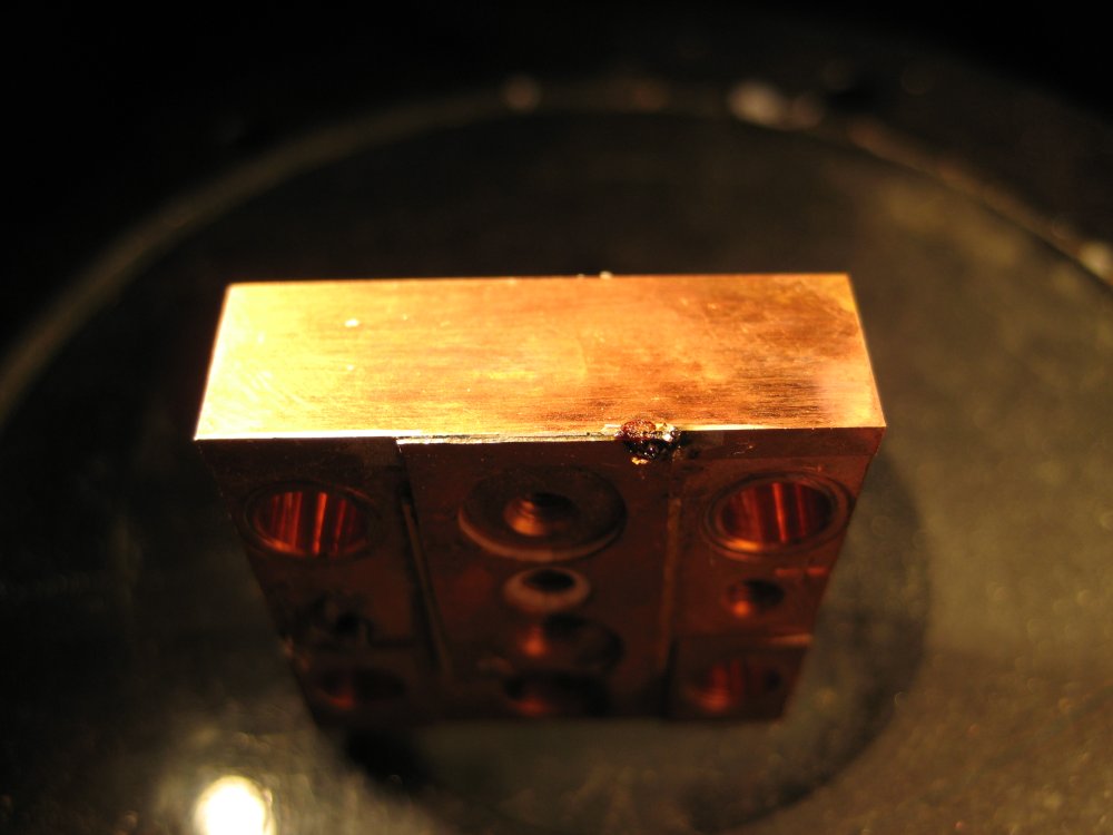
Next up was the diode bars, which are essentially 19 laser diodes that have not been cleaved apart yet. This is both good and bad, on the one hand they are much easier to handle than the individual bars, but on the other hand it means that the solder has to be perfect across the entire bar, if there are any voids the emitter above the void will overheat and short out the entire bar.
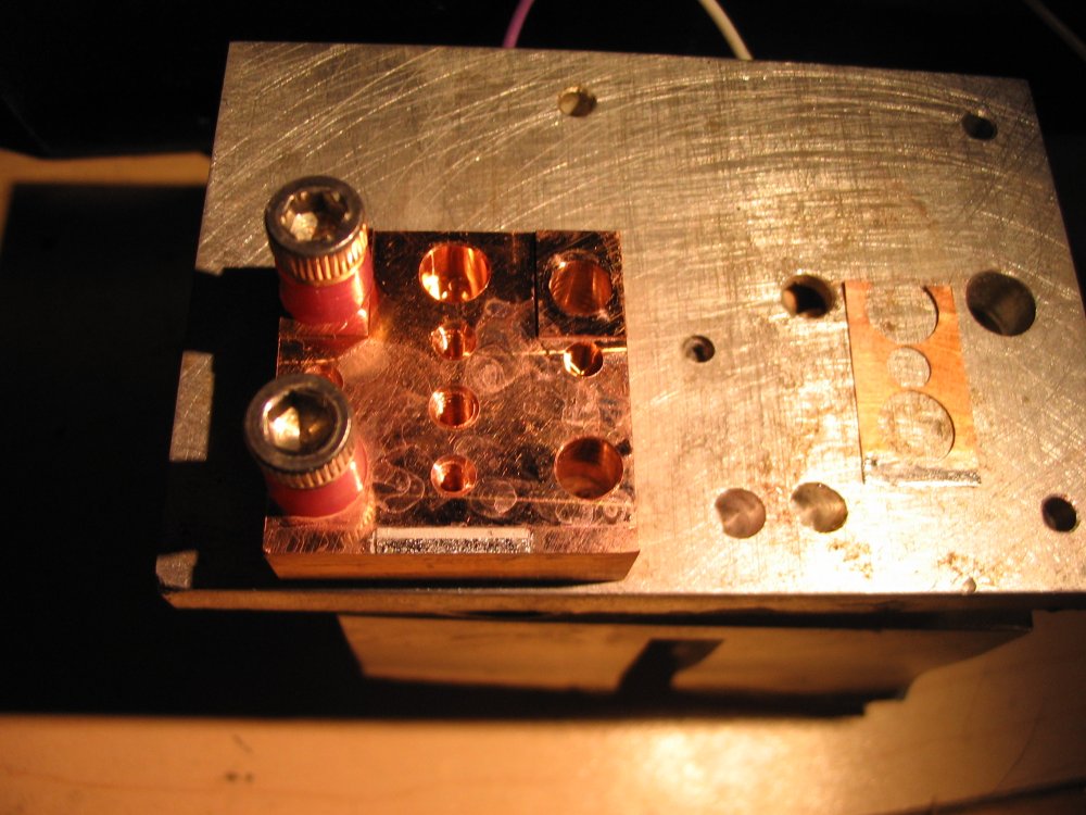
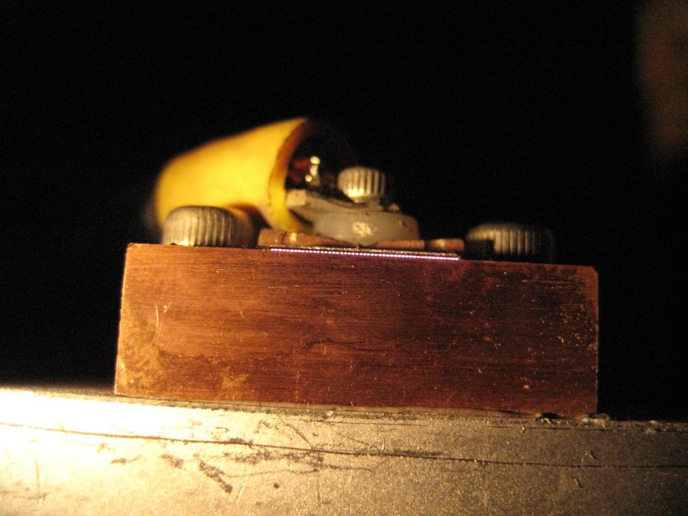
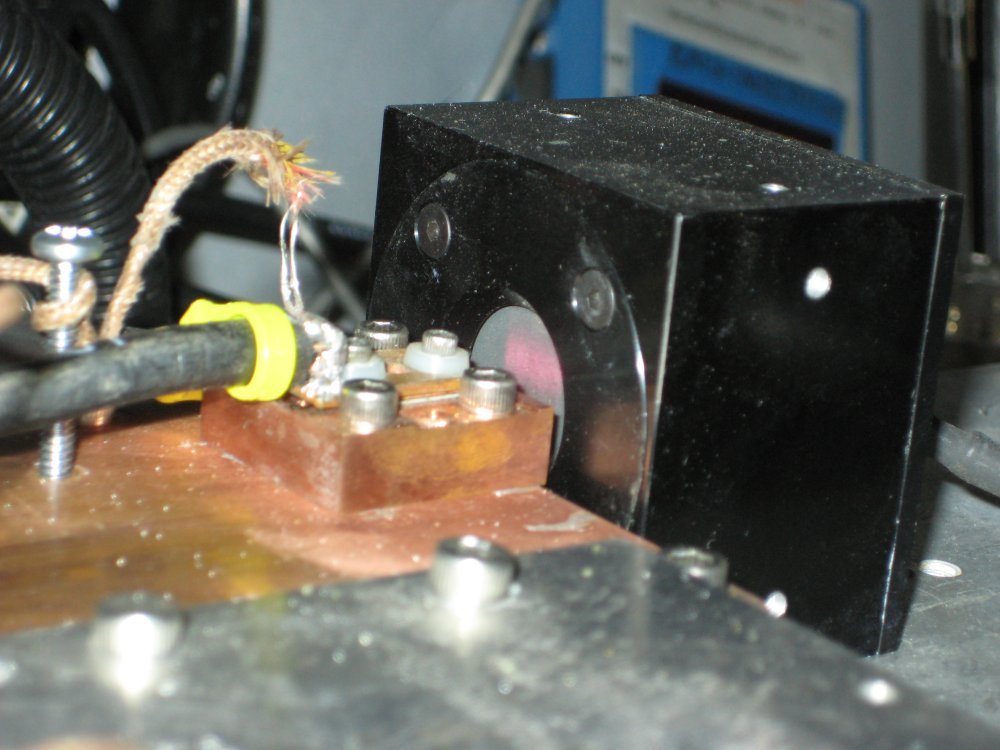
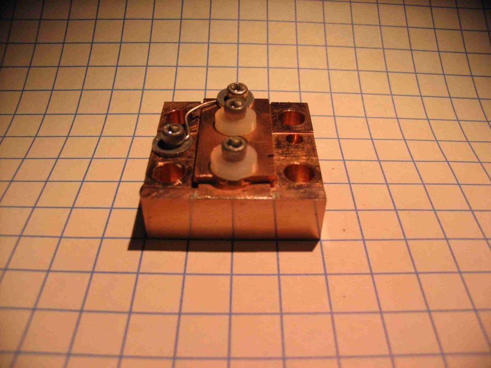
First, I put the copper mount on the heatsink, held it down using some socket head cap screws with a piece of 1/4" silicon tubing (to act as a crude spring) and let everything heat up. Then, I wiped the surface with a flux soaked q-tip, quickly dabbed some solder, and wiped it around with the q-tip to tin the surface. The q-tip also served to remove most of the solder, ideally only a very thin layer is required--too thick and the solder oozes out and can short out the bar. Then, the same procedure happens for the top of the bar, and the electrical contact (piece of copper sitting the right of the bar on the hotplate)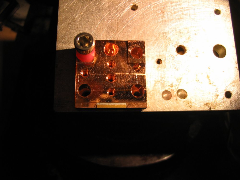

I can be contacted at contact@krazerlasers.com