This project started out as a curiosity, and quest to build a whitelight laser for a reasonable budget (estimated cost for the laser source is $100). I then chose to use it for a project class (ECE 94R at UCSB) and added set of galvanometers and a controller for the system based on an Arduino microprocessor. The project has probably 200hrs of work in it (150 for the various revisions of the rgb source and 50 for the electrical design and programming), and about $300 in parts that went into it (about $150 in laser diodes--only $60 worth of which are in the final system, $100 for the microprocessor and lcd, $30 for the galvanometers, and $20 in odds and ends).
For more information of the class, see the class website, and for more information about the laser source see the pages devoted to them: RYG laser I RGB laser II RGB laser III
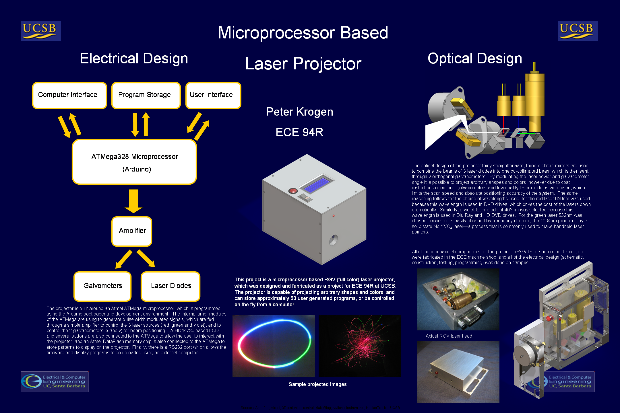
The design of the projector is highly modularized, and can be easily broken down into the RGB source, Galvanometers, Controller, and Software.
The RGB source was the hardest of this project to create, and I spent about 2 years working on it on and off. The concept is simple--take red, green, and blue laser diodes, and use dichroic mirrors to combine them into a single beam, which would be sent to the galvanometers.
In practice, as the first two revisions of the laser module show, this was not so easy. In order to keep the beams coincident, which is absolutely necessary for proper color mixing, they must be all kept aligned in the x/y/z axis to within about .05" or so, and 0.03mRad in pitch/yaw. This second figure is much harder (that is .1" over 30ft), and is a result of the fact that the divergence of the laser beam is on the order of .2mRad so to keep the beams at least somewhat coincident .03mRad is the max error you can use. To put that in perspective, if one of the edges of the 1/4" square mirrors moves 1/15,000th of an inch, the beam will not be aligned any more.
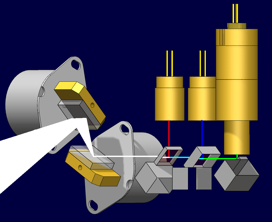
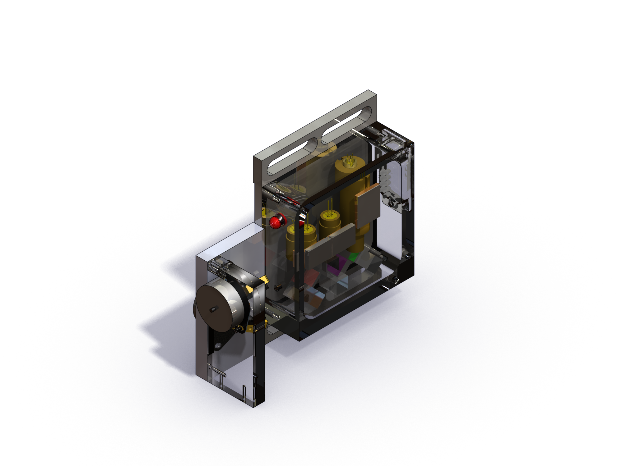
That said, to get around this problem I machined a pocket in a 2" square by 1" thick aluminum, and use uv curing epoxy to hold the optics in place:
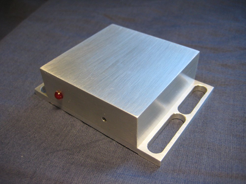
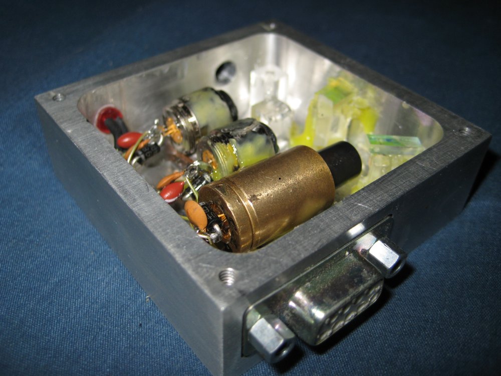
(for more photos of the system, see the RGB laser III)
The lasers themselves would be to costly to buy from a laser manufacture, so alternate sources of the lasers were found. For the red laser, I used the 650nm laser diode found in a high speed DVD-burner, for the blue laser I decided that the violet laser found in a blu-ray or hd-dvd burner would suffice, and for the green I used a dpss module extracted from a 50mw hand held laser pointer.
The controller for the project is electrically quite simple, and most of the grunt work is done in a microprocessor. The hardware timer modules in the Arduino microprocessor are used to generate 5 PWM modulated signals, 3 of which are used to control the laser intensities and 2 are used for the galvanometers. To actually drive the laser diodes a constant current source based on a LM317 voltage regulator is used, and a small mosfet is put in parallel with the laser diode--such that with the mosfet is it will divert current from the laser and blank the laser. The mosfets are driven directly from the PWM outputs of the Arduino, and as a result the lasers are actually being pulse width modulated. However due to the fast PWM outputs of the Arduino (32KHz) and slow scan speeds, this effect is not noticeable in the scanned images. Similarly, to drive the galvanometers, the PWM output from the Arduino is fed through a small amplifier (actually designed for driving mosfets), which is then fed to the galvanometer. Through careful biasing of the galvanometers, it is possible to get both a positive and negative scan angle using this technique, and due to the high momentum of the galvanometers they effectively filter the PWM signal and respond quite linearly. The microprocessor is an Atmel ATMega328, which has the Arduino bootloader and code written using the Arduino IDE, which controls all of the components of the projector. Due to the limited storage available on the Arduino, an Atmel DataFlash chip was added, which allows about 50 programs that have 4000 points in them (about 4s of continuous scanning) to be stored. Finally, a 4x20 character LCD and simple up/down/select user interface was added to allow programs to be easily selected. Finally, there is a manual mode where the Arduino simply accepts coordinates from an external computer over a RS-232 compliant serial port, which allows for longer and more complex programs to be displayed.
The firmware for the projector is written Arduino, which while not my first choice is what the class was based on. The main loop in the code reads coordinates from the DataFlash and updates the galvanometers and lasers accordingly, then waits a period of time defined by a 5th coordinate saved in DataFlash. Additionally, there a program selector logic, which displays each program's name on the LCD display, and allows the user to scroll through them using an up/down pushbutton. Additionally, there is a random mode which uses a simple random generator, based on a multiply-with-carry random number generator, which displays pseudo-random abstract shapes, a manual mode which projects coordinates received from an external computer via a serial port, or a test mode which displays a simple circle made up of several colors. The code is still somewhat beta, but it can be downloaded here.
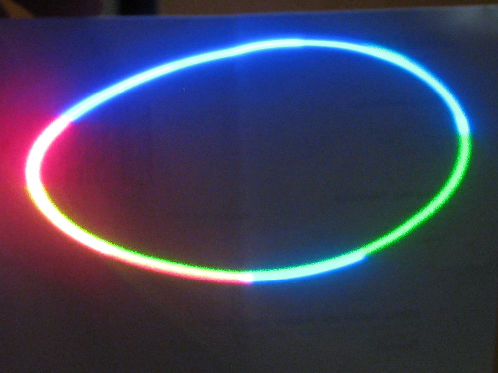
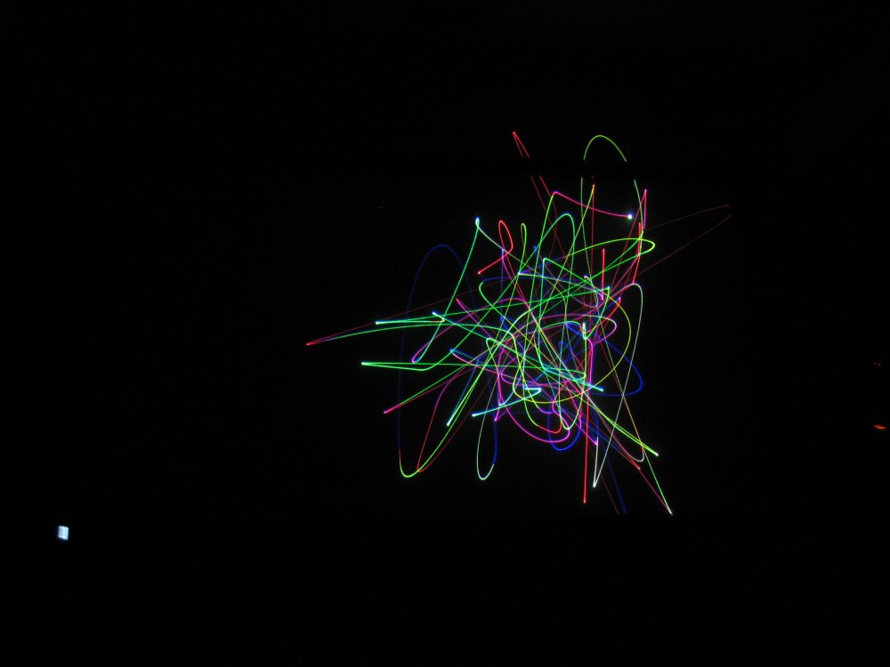
The test pattern (projected on a piece of paper because my camera cannot see the 405nm on a non-fluorescing surface) and the random data.
All considered, I learned a lot in making this project, and definitely have plans for a rev 4 (although probably not any time soon). I encourage you to try a project like this, however it is not something that you can throw together in a weekend and have a really decent working project. I really enjoyed the construction process, and the projected images are amazing. The pictures really do not do it justice, the color gamut obtained using 405nm and 650nm is incredible, and computer monitors simply cannot display the range of colors this thing produces. Especially the random mode is very mesmerizing, and it can fill half a room with ever changing patterns of brightly colored lines. I hope you enjoyed reading about it!
Licensing:
Everything on this site (pictures, schematics, code, etc) is licensed under a Creative Commons Attribution-Noncommercial-Share Alike 3.0 United States License, which essentially states that you can do whatever you want with it, so long as you
If you need a different license, contact me.
questions? comments? Want to help? email me contact@krazerlasers.com