This project started as a ProjX project that I did in my free time while I was at MIT. After the issues with my first, second, and third RGB laser projectors, I decided to incorporate some adjustability into the design so that the alignment of the 3 laser beams could be tweaked as the system drifted. This meant that the requirements on the system during the initial construction (requiring a complicated alignment jig and high performance epoxies) were greatly reduced, and allowed me to use much 'squishier' materials for the system construction since if the alignment of the beams drifted it just took a few seconds to tweak their alignment. Furthermore, since MIT is big on rapid prototyping I decided it was a good opportunity to see what all of the fuss was about and fabricate this design using 3D printed parts. The end result turned out pretty well considering the whole project was done in a bit under 3 months (from applying for funding to final demo), with all of the mechanical work (printing, assembly, alignment, etc) completed in a weekend. Finally, while not required by ProjX, I decided to only use Free and Open Source (FOSS) tools for this project (FreeCAD, KiCad, Slic3r, LibreOffice, etc running under Linux) and found the process to be pretty pleasant and hope to largely keep things this way for the other projects I work on.
My goal for this project was to have a projector was was easily reproducible and affordable, so that any hobbyist should be able to reproduce it without too much trouble. The final cost (excluding the cost of the 3D printed parts) came out to about $200 for the module, which the needs laser drivers, scanners, and some sort of DAC to be used a complete laser projector. The final output power is about 200mw of balanced whitelight (the diodes I used were a bit heavy on the green and blue) after the losses in the cheap dichro mirrors I used, which is plenty for graphic scanning, or small beamshows in a dark room with medium to heavy fog.
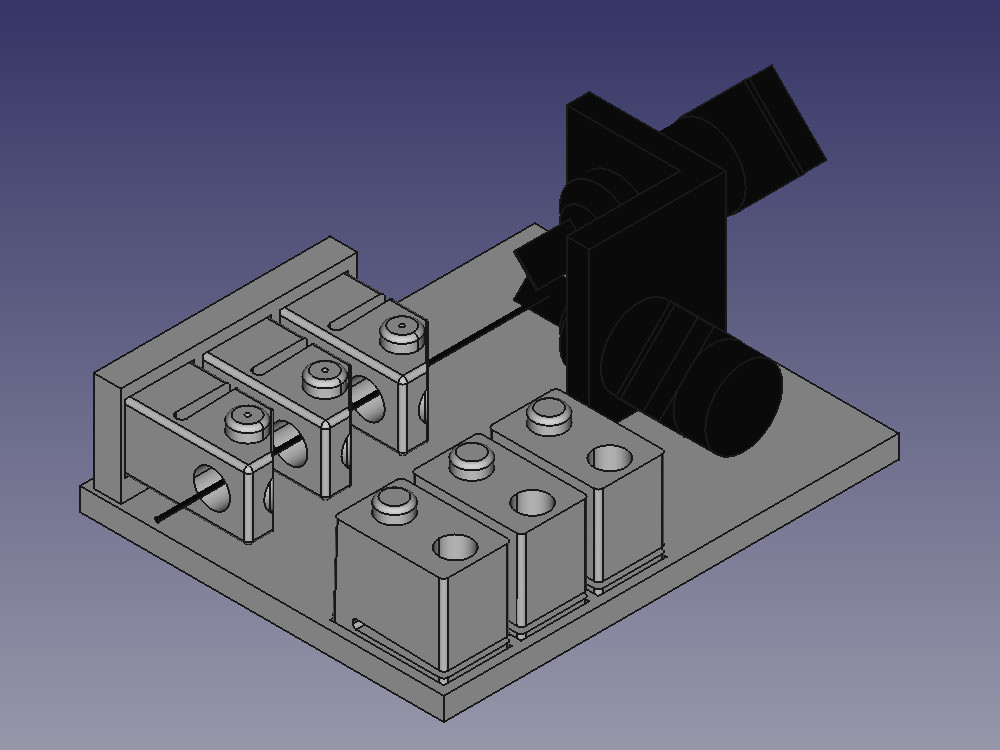
I designed the module so that it had vertical and horizontal tilt adjustments for each of the 3 laser channels (to allow alignment of their collinearity), but I did not make any effort to allow translation of the beams. I found that as long as the beam path lengths were short enough the slight centering errors were negligible compared to the laser beam diameter, so by adding alignment references into the 3d printed parts it was not necessary to allow adjustment of the beam centering. I did however decide to print the module as 7 separate pieces (a baseplate, 3x laser mounts, and 3x mirror mounts) to ease the requirement on the 3d printing, and to allow the flexure mounts to be printed so that the flexure was in the X-Y plane of the 3d printer so there was no risk of the flexure joint failing due to poor layer adhesion. To simplify the design, I only put one flexure joint per part, with the vertical pointing adjustment incorporated into the laser mount, and the horizontal adjustment in the mirror mount. I printed the parts in ABS on a Solidoodle 2 printer, so I think that any modern 3D printer should be able to print the without too much trouble. Furthermore, I added an aluminum baseplate under the 3D printed one, which adds a huge amount of rigidity to the assembly and makes it mechanically quite stable. There is a bit of 'creep' in the alignment since the ABS slowly deforms over time, but a quick tweak of the alignment screws can correct for this. The final design (drawn in FreeCAD) is shown below, and there is a complete set of design files including .stl solids and a BOM here.
In order to make sure that everything would arrive on time for the ProjX deadlines, I decided to source all of the mechanical components from McMaster Carr, and the optics from Newport, but you can get the cost down a bit if you scrounge on eBay and the likes. I ended up ordering the diode modules from DTR's Laser Shop since they were much cheaper than from a legitimate optics dealer, and come pre-mounted in 12mm modules which should make the system a lot easer to work with for people new to optics. For the laser drivers, galvo scanners, and DAC I borrowed the control system from my RGB Projector II. The fact that now in 2016 you can buy a full set of ~100mw red, green, and blue laser diodes for $100 really shows how far the state of the art has advanced since I started this hobby back in 2006 when true blue diodes cost thousands of dollars and a direct green laser diodes (as opposed to the common 532nm DPSS lasers) were not for sale at any price...
The construction of the system is fairly straightforward, consisting of printing the parts, a few glue steps, and then final assembly.
First, print out the baseplate, and cut a piece of aluminum to size (In the BOM I included a link to a 3" by 6" by 1/4" thick piece of aluminum from McMaster Carr, which is about the same size as the 80x100mm baseplate, but will overhang about an inch on one side if not cut down).


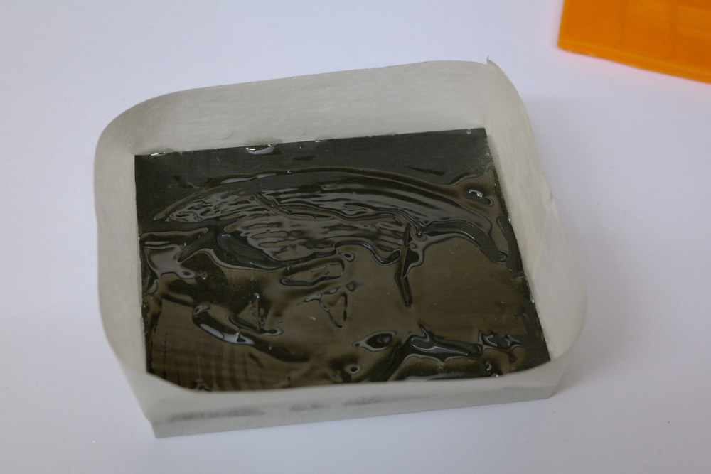
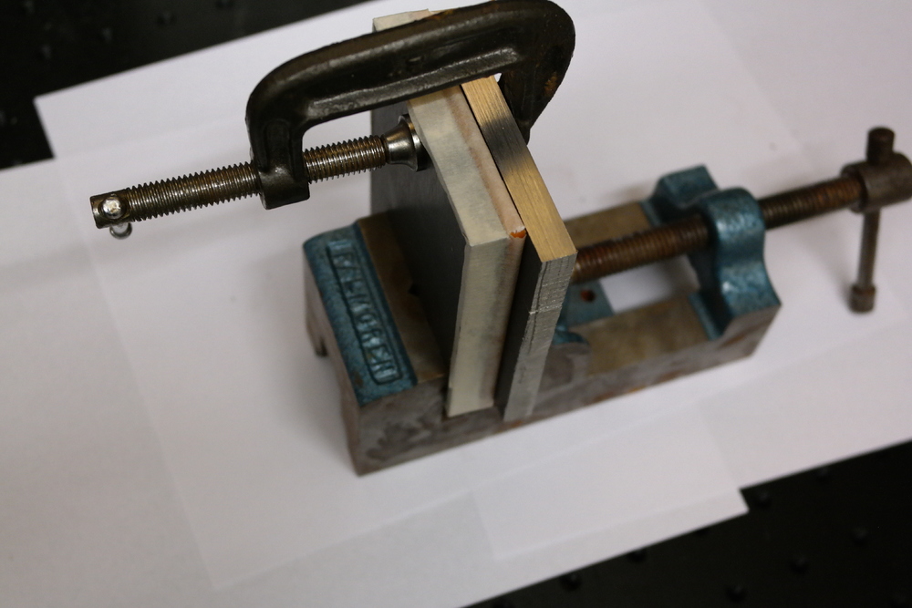
Next, put a wrap of tape around the aluminum plate (to keep the epoxy from getting everywhere) and cover the plate in epoxy. The baseplate had a significant amount of warpage when I printed it on the Solidoodle, so I used a thick layer of epoxy to fill in the uneven bottom surface. Finally I clamped the two pieces in a vice with a scrap piece of aluminum against the 3D printed surface to keep everything true. A stack of books would also work fine for this if you don't have a vice handy...
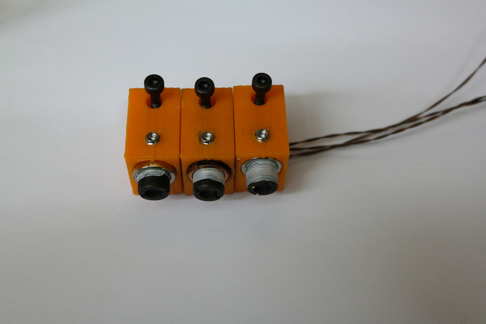
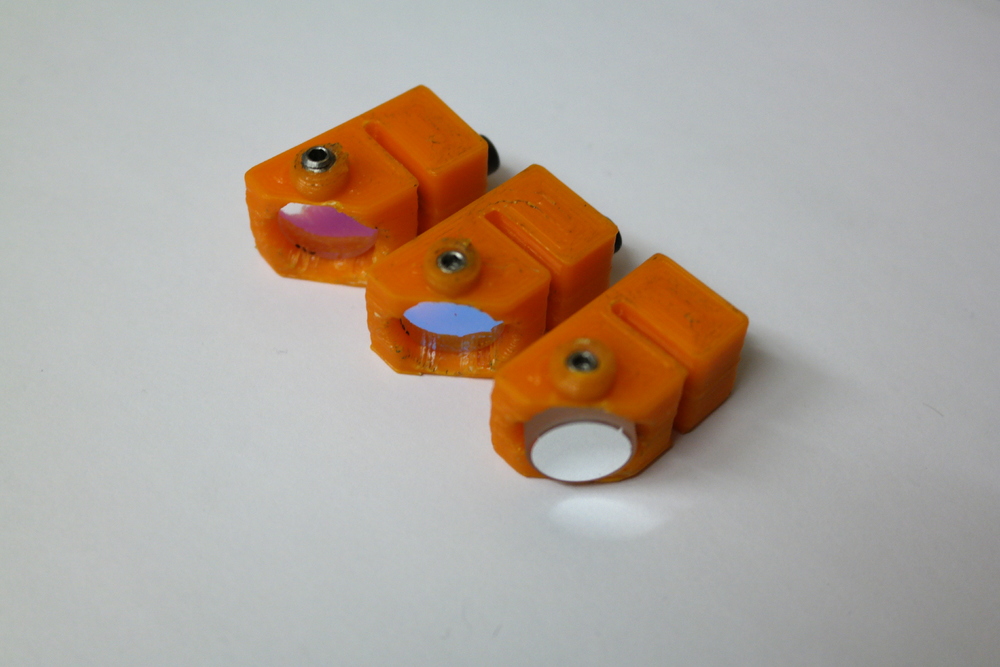
While that cures you can print out the optic and laser mounts:
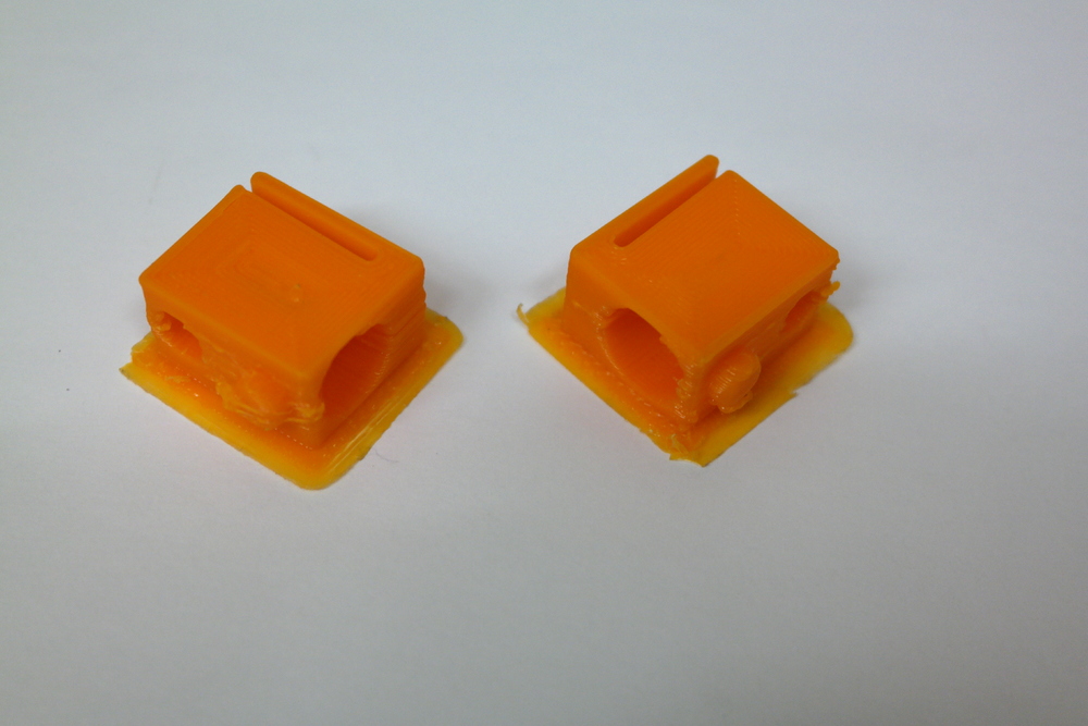
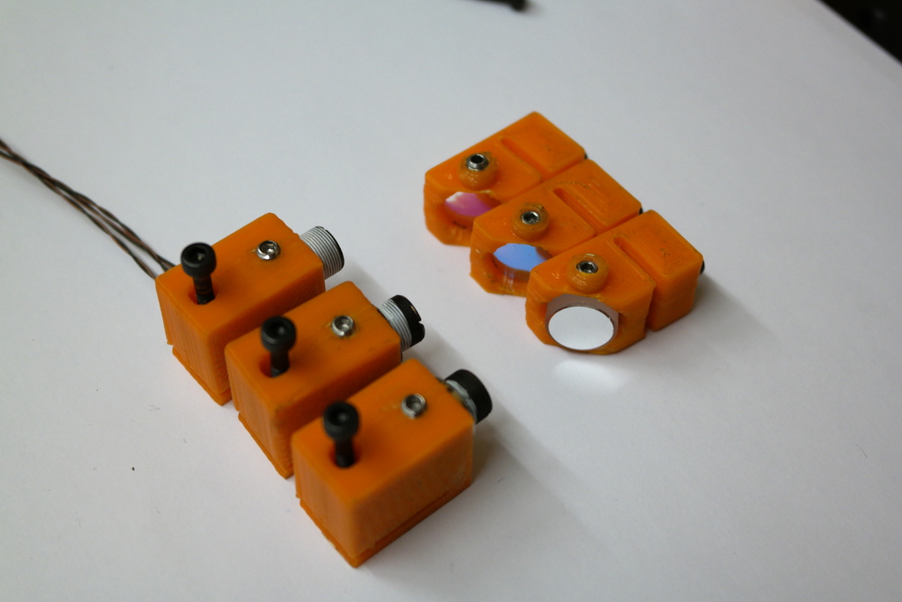
And load up the laser modules and mirrors... I did not try to 3D print the exact hole sizes for the screws, instead printing a small pilot hole and using a drill to expand them out to the proper size. If you have faith of your 3D printing skills you could modify the parts to avoid this step. You will note that in the third mirror holder I used a much thicker mirror (this is a fully reflective metallic mirror, since it is the first mirror in the optical path it does not need to be a dichroic), this turned out to be a pain so I changed the BOM to include a third dichroic mirror so that the optic thickness is the same for all 3 of the mirror holders. You can also see the adjuster screws here, tightening them stretches out the flexure joint. I found that hitting the ends of the screw with a file to round over the end made the adjustments much smoother, but they work fine as from the factory. The parts are printed with a few degree angle in the flexure joint in its relaxed state, so they can be tightened to bring the flexure to a neutral position allowing adjustment in both positive and negative directions. However, since the bottom of the laser mounts is very thin it will flex before the flexure does, so it should be glued down to the baseplate in its relaxed state
Next, glue the mirror and laser holders to the baseplate, using the depressions as an alignment guide. I found that it was worth it to install the mirrors and laser before the gluing step, so that you can run the lasers at low power to check the course alignment of each beam while there is still time to correct for any errors in the 3d printing. For the glue I used acrylic cement, but ABS pipe glue would also work well. I would not recommend using epoxy since I have had bad luck bonding ABS with epoxy and the flexure joints in the laser mounts put a good amount of stress on the glue joint. If you do decide to use epoxy I would suggest roughing up the glue surfaces and wiping them down with some rubbing alcohol to remove any contaminants before gluing to maximize your chance of success.
All thats left is to power everything up at low power and do the fine alignment of the beams using the 6 flexure joints by looking at the laser spot a few meters away from the projector. I found that it works well to use a large mirror on the other side of the room to reflect the beam back toward yourself (of course only do this at low power and don't aim the back at eye level!) so that you can clearly see the 3 beams overlapping on each other. You may also need to tweak the focus of the laser modules to get the beams to be about the same size in the far field.


Finally wire up the laser drivers and mount the scanners. I set the beam height so that the cheap Chinese scanners on eBay can directly glue onto the baseplate. Well at least I thought I did, it turned out to need a small shim.

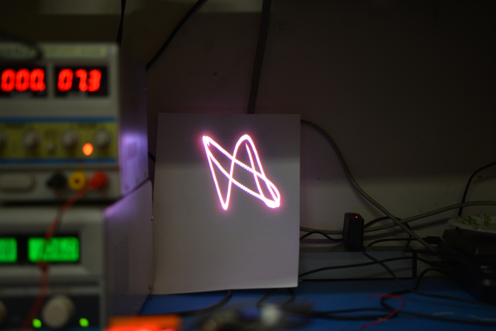
These images were taken using my RGB projector III projector design, which is based on an open DSP based galvo driver (still in its early stages).
Licensing:
Everything on this site (pictures, schematics, code, etc) is licensed under a Creative Commons Attribution-Noncommercial-Share Alike 3.0 United States License, which essentially states that you can do whatever you want with it, so long as you
If you need a different license, contact me.
questions? comments? Want to help? email me contact@krazerlasers.com